![]()


It seems like it has taken me a long time to get to this point. But here I am to overview the Star Tracker Beta camera mount which is the final component of the minimum viable product. Once this is complete, I’ll be able to begin testing the star tracker. And just in time too! It’s the end of May here in Poland which means the gloominess of the perpetually overcast skies is finally giving way to ever clearer weather. Cygnus is rising nicely in the East which means Andromeda will be hot on its tail. What a great time of year to be involved in this hobby!
The Road Thus Far
I think now is a good time to summarize what it has taken to get to this point of the project before revealing the final component. I focused on a modular design so I could refactor and redesign elements on the fly. And the principle components of Star Tracker Beta are as follows:
I suppose it’s worth mentioning the gears as well. I probably should have written a whole post on the gear system but it’s a bit late now. I can tell you that I designed a compound worm gear arrangement with a module factor of 1.5 to deliver a 256:1 gear reduction. This is all the juice I need for this project, but I did find a problem right here at the end. Of course… I can tell you that Star Tracker Beta is going to be a viable star tracker. But I had a big design oversight that will likely facilitate the design of a Star Tracker Gamma. I’ll let you try to guess what that is but it will make its grand appearance when I actually start testing. It’s all part of the fun!
Star Tracker Beta Camera Mount
But I digress. Let’s finish this MVP star tracker build! So the last major component to design and print is the star tracker camera mount. There are a few design considerations here. First, I want this component to be removable. This will make it easier to travel around with this mount. Second, I want the camera mount to clamp onto the main drive shaft instead of locking onto the shaft with set screws. And finally, I want to use the 10mm aluminum tubing as the counterweight rod. This will require a little thought as to how I want to attach the rod to the camera mount. It would be great if that can be removable as well, but that’s not a requirement at this point.
Getting a Little Help
I was sure that I was going to need a thrust bearing to support the camera mount if I was going to have this component be removable. So I headed on down to the bearing shop Arteks24.pl down the road from me. Talk about a unique place! They have anything you could possibly want in terms of bearings and belts. It’s a total nerd trip.

Anyway, I took Star Tracker Beta along with me so I could show the guys. I wanted to make sure I was asking for the right thing. So after explaining my design requirements and asking for a suitable thrust bearing, these guys steered me in a different direction. I was informed that the loads and load types that I’d be carrying really didn’t require a thrust bearing. What I really needed was a couple of needle bearings instead. And of course, they had just the thing – a pair of Koyo needle bearings which slipped nicely into place over the main shaft. How cool is that?
So time for a quick plug. If you find yourself in need of any bearings for your projects, I can’t recommend these guys enough. Friendly, knowledgeable, and experienced. If you’re in the Krakow area, head on over or you can check out their online store.
The needle-bearing solution for a removable camera mount is going to work out awesome for this project. Now onto the other requirements.
Clamp It Down
You’ll recall in the counterweight design post that I’m trying to design a clamp that will grip the aluminum tubing instead of screwing down onto the shaft. I’m going to use the same design principle for the camera mount. The only tricky thing here is to ensure that the clamp will fit between the needle bearings and be positioned in such a way as not to compromise the integrity of the camera mount. The last thing in the world that I want is to have this thing snap apart in the middle of an imaging session.
The good news is that this clamp won’t experience a high axial force when locked in place. This is a function of properly balancing the star tracker. Mental note, always make sure the camera mount is properly balanced when working with the camera!
No More Threaded Rods
As we saw with Alpha, there was way too much flex in the threaded rod to stably balance a counterweight. I suppose as long as there was no wind, things were fine, but the second a little breeze kicked up… Forget about it. So the big change in Beta is the move to use the 10mm aluminum tubing. Now, this also has a small amount of flex to it, however, it’s much more rigid than the threaded rod.
The only question to really answer here is how I want to attach this to the mount. I did have dreams about attaching a bolt at the top of the tube that I could screw into the camera mount. Or a twist and lock-in-place design. But I totally wussed out. Right now, it’s more important to me to have the counterweight rod be tight and stable. I can achieve that with a slightly undersized borehole and 2 screws drilled through the top of the tube. Now I don’t need to worry about this wobbling or coming loose during shooting.
The Big Reveal of the Star Tracker Beta Camera Mount
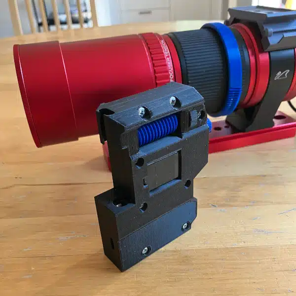
Alright, here it is. The final component that is necessary to achieve a minimum viable product state for Star Tracker Beta.
 | |
The pan clamp on top is held in place with 4 M4 screws. 2 Needle bearings are press fit into the main shaft bore. The clamp is secured with an M4 screw and tightened with a similar M4 knob screw that was used in the counterweight design. The counterweight rod is attached using 2 M3 screws drilled through the top of the tube. Here’s a closeup of one of the needle bearings and a picture of the camera mount attached to Star Tracker Beta.
 |  |
A quick test of Alpha’s electronics box proved to be successful. So there we go. I’m ready to rework the code a little bit and start testing. Star Tracker Beta has officially achieved a minimum viable product status. Whoo Hoo!
On Deck
I’m sure you could have guessed that by the time I’m publishing this post, I’ve already had an opportunity to do some quick testing. I’m not going to spill the beans here, but I’ve got a lot to write about in the near future. What I can tell you at this point is that I’m still learning, still tweaking, and still having a lot of fun.
I’m also going to write a little bit about two new additions to my astrophotography gear. I recently received an Omegon Polar Wedge and an Optilong L-Pro Canon APS-C clip-in filter. I had very specific reasons for making these investments at this time and I’ll share those considerations shortly.
So I have a lot of exciting things going on. Just about the time the weather starts clearing up a bit around here, I find myself falling short of nighttime hours. But it’s nice to do a little shooting in shorts now and my battery is certainly loving the milder temperatures at night. So stay tuned as there’s a lot of cool stuff on deck.

Heyo how do you align your setup. You have the polar star in the northern hemisphere. We sadly only have a very very faint sigma octant, who I only guess I find if I do the southern cross thing with a laser pointer.
I have not found any mentioning of calibrating setting up your system, maybe just missed it.
Hi Guido, I applaud your attention to detail in your reading. I don’t talk a lot about how I calibrate because quite frankly, I’m still working it out. But here is the process that I’ve been using for the past few months. I carefully align my camera with the drive shaft of my tracker and use SharpCap to do my polar alignment. I use the ASCOM driver for DSLRs and the polar align tool to work through the alignment. I can’t recall, but I seem to remember that SharpCap costs about $20 per year. I can tell you that I definitely feel as though I’ve got my money’s worth with this program. Once I’m happy with the alignment, I point the camera to my target and run my session.
Is it perfect? No. Is it more than good enough for where I am right now imaging between 50-135mm? Definitely. I’ll be the first to say it’s probably not the best idea to try to polar align with your imaging camera. I’ve toyed with the idea of deconstructing a webcam that I can mount to the tracker to perform a more precise alignment. But polar alignment hasn’t been my biggest issue with my DIY tracker adventures. For what it’s worth, I can get away with this now because of how I’m mounting my camera on the tracker drive shaft. And this is the reason that I’ve ditched my ball head in favor of a pan clamp. A lot less that can go wrong with lining things up to perform my polar alignment this way.
I’m sure I’ll move in a different direction in the future, but it works just fine for me right now. But take a peek at SharpCap to see if that might help with your alignment.
Good question though, thanks!