![]()


There was a fair chance of getting outside tonight but it appears that will not be the case. While the current forecast says intermittent clouds, it looks more like intermittent skies to me. I may check one last time in a little while, but I’m expecting the Sandman to come calling at any moment. So since I can’t be outside right now, I’ll just write up my first post on my next gen 3D-printed star tracker. Let’s just call this one Beta to make it easy. I don’t want to give too much away with this one yet, so I’m going to start small and provide the details surrounding the worm gear motor assembly. I figure that’ll be enough of a tease for now.
Worm Gear Motor Assembly Objectives
In my first 3D-printed star tracker design, I had to make a plug rod to hold the main worm gear in place. This wasn’t ideal for a number of reasons. First, I’d probably need a stick of dynamite to take it apart if I ever needed to. Second, the bearing was seated in the worm gear which ended up being about as stable as a Weeble Wobble. And finally, you need to have a black belt in patience to actually install it. All this points to the need for a better solution.
I’m designing Beta using a modular approach. While this will add some complexity and make the printing a little more difficult, it should in theory overcome all the aforementioned issues. I’ll build several modular components that will screw, snap, slide, and lock together to form the final project. And the first component that I set out to tackle was the motor assembly for the main worm gear.
Basic Design Idea
So the whole idea of creating a component that will secure the stepper motor and the main worm gear sounds pretty simple. And it is actually. The tricky part is thinking about how I’m going to plug this into the tracker. Here is where things start to get exciting…
I want the component to be held firmly in place without the possibility to shift around. So I can design the component to cut into the wall and the tracker base. When using a printing margin of 0.25mm between connecting parts, this will provide a good tight fit into the tracker. I’ll then secure this in two ways. First, I’ll mount two M5 hex nuts in the component base that accommodate screws from the underside of the tracker. Second, I can use the rear main shaft bearing to pin the whole assembly in place. Here is the FreeCAD image of the main element of the worm gear motor assembly.

Notable Features
You will immediately notice that the stepper motor and the small worm gear bearing will slide into the assembly at a 45-degree angle. There are a few reasons for this. First, I want the main worm gear to align with the main shaft without contacting the main shaft. Turns out that a 45-degree rotation is ideal in this case. Second, I’m leaving a little lip on the motor bracket for the stepper motor to really snap into place. Third, I need to have a small track built for the small bearing so everything can slide into place. I have a plug to seal this track that is held into place by both the main housing wall and the rear main shaft bearing. You’ll see that more clearly when I assemble the whole tracker.
Putting The Worm Gear Motor Assembly Together
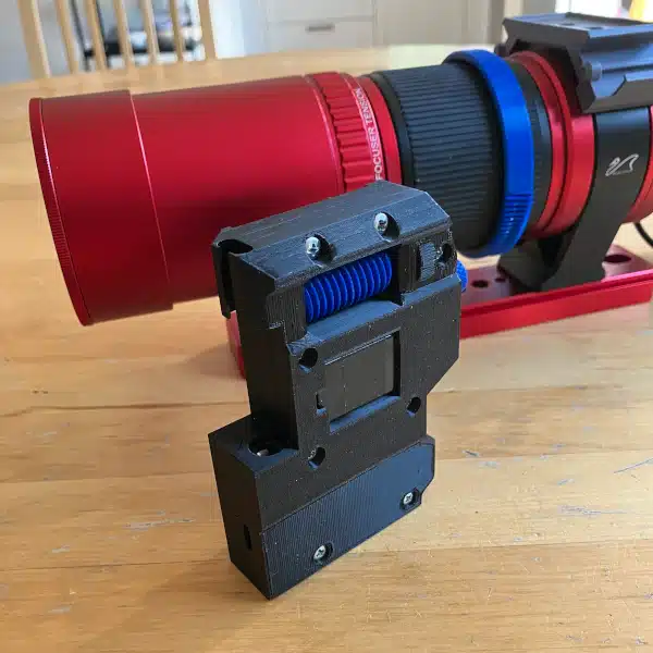
All told, I spent about 4 hours printing 3 parts for this component. There is the main motor assembly body, the worm gear, and finally the bearing track plug. The only thing I’ll note here is that I spent about 2 additional hours sanding the crap out of the worm gear. I want these gears to be as smooth as a baby’s bottom so I won’t have any printing step changes showing up in my photos. Below you can see all the parts needed for this component.

In addition to the printed parts, I am using; (2) M5 hex nuts, (2) M3 20mm screws, (1) 5x9x3 ball bearing, and of course (1) 28BYJ-48 stepper motor. Putting everything together was a breeze. Here’s the sequence.
| 1. Press the M5 hex nuts into the main motor base assembly. The hex nuts should fit snuggly in their cutouts. |  |
| 2. Press the bearing onto the worm gear and slide the worm gear onto the stepper motor shaft |  |
| 3. Carefully guide the motor and bearing into place. The motor should lightly snap in when fully seated. |  |
| 4. Secure the motor with the M3 screws and slide the track plug into place. | |
Voila, done! Now you just have to wait to see how this fits into the overall star tracker project.
Next Steps
So that’s the first element completed for Beta. I’ve actually already completed the main housing for the star tracker and plan on getting that assembled with the gears. Look for a post on this later this week. Right now though, I’m just sanding, sanding, sanding all the parts.
Oh, and in case you’re wondering. My computer is telling me that it’s clear outside right now, but the sound of the rain pinging my skylight makes me extremely skeptical. Facepalm! Well, maybe tomorrow I’ll have some better luck.