![]()

It’s been a while since I last posted. You can probably imagine that the last two weeks have been a little bit crazy for us here in Poland. Yet, in times like these, it’s important to preserve a modicum of normalcy. So in the meantime, I’ve been making slow and steady progress with my 3D-printed star tracker. In fact, I’m happy to report that I’ve completed the minimum viable product (MVP) build. So today I’ll share a little bit about the basics of my design but I hope to publish a lot more in the coming days as I have an opportunity to upgrade and refine my design.
From the Beginning
I mentioned in a previous post that I’ve taken a lot of inspiration from a brilliant instructable created by Simon Rob. If you’re looking to build your own 3D-printed star tracker, I suggest you check his site out. You’ll learn a lot about the methods and engineering principles involved and he does a good job explaining what he did. For my part, it was the simplicity of his design that I was initially drawn to. However, I knew I was going to want to make some changes – of course :).
Higher Resolution of Movement
Simon Rob built a 6:1 gear reduction on the output of his stepper motor. This is fine, but I had 2 concerns about this for my design. First, I was concerned that the torque would be too little to drive the tracker when I mount something like my Samyang 135mm lens. Second, the maths require that you can only step the motor every few seconds (3.5 seconds in fact). For a 135mm lens, that’s going to result in seeing star trails in the photos which I don’t want!
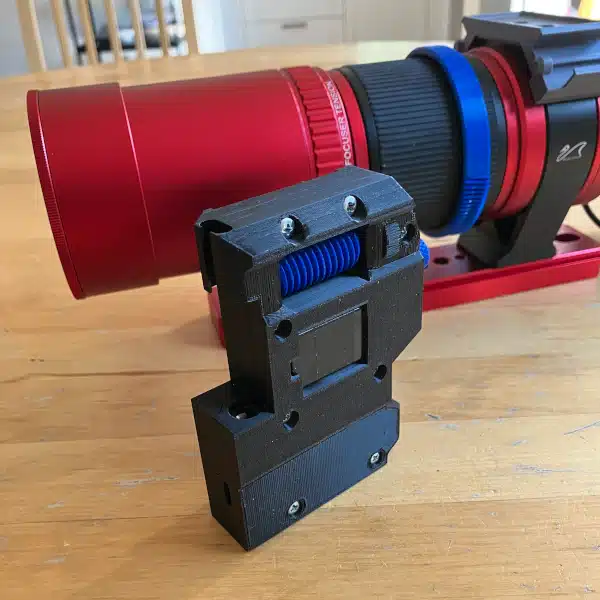
I decided to design my 3D-printed star tracker with a much higher gear ratio to get around both of these limitations. It was important for me to get the maximum gear ratio with the least amount of interlocked gears. Naturally, worm gears are best suited for this but they also come with their own challenges. Namely, I’ll have to deal with friction and thrust forces. And, I’ll need to think about how to balance the camera arm since I can’t disengage the worm drive. But, to keep things simple, I decided to stack two 10:1 worm gear trains to yield a 100:1 gear reduction.
Part Positioning
Since I’m using worm gears, I’ll save a lot of real estate in my design. To keep things as compact as possible, I decided to mount my motor and gears between my ball bearings rather than from the rear of the device. It’s a small swizzle, but I want to build something extremely portable.

Wedge Design
I suppose I could just print a wedge mount with a fixed 50-degree angle and I’d be fine. But where’s the fun in that. I decided I wanted to print a wedge mount that would allow for some fine movement control. It took a while to design, but I finally got it kind of working. That said, I know I’m going to have to modify this a bit moving forward but this isn’t a priority for me.

Arduino Code Upgrades
With all due respect and credit to Simon Rob, I believe he biffed a couple of minor details in his code. I walked through the CheapStepper.h library code and learned that there are a couple of settings missing in his code that are important if you’re striving for operational precision. I have every intention of sending that information to him when I can confirm these issues through testing. Without going into all the details, it’s important to respect the blocking nature of the library which requires that the step velocity is respected – ie. the RPM of the stepper motor. Also, the number of micro-steps of the stepper motor defaults to 4096 in the library but was measured as 4076. It was Simon Rob’s intention to use 4076 steps, however, this needs to be explicitly called in the code to take effect which was missing in his code sketch.
3D-Printed Star Tracker Design Basics
Ok, I’ve gone into what I wanted to redesign, now let’s talk about the maths surrounding my redesign. I am going to play fast and loose with a couple of these numbers as you’d be right in noting that I’ll never achieve the precision of the numbers I’m working with when considering how I’m building this device.
Earth Rotation
The Earth rotates 360 degrees once every 86164.09 seconds or just short of 24 hours. Therefore, the Earth rotates 0.004178 degrees every second or 0.25068 degrees per minute.
Gearing Down the Stepper Motor
The stepper motor has 4076 steps per 1 revolution. My gear train has a gear reduction of 100:1. Therefore, 407600 steps on the motor will equal 1 revolution on the output. This means that for every step of the stepper motor, the output will rotate 0.000883 degrees.
If I want the output to rotate by 0.25068 degrees per 60 seconds, I need to drive the stepper motor 283.8255 steps. This means that every second, the stepper motor needs to move 4.730424 steps. If I divide 1 second by the number of steps, I determine that I need to take one step every 0.211398 seconds.
Stepper Motor RPM
The stepper motor defaults to 16 RPM but can be adjusted in the sketch if desired. I’m not inclined to tweak this at the moment but reserve the right to change my mind in the future. Why is this important? I want to keep my code simple at the start so I’m going to use blocking commands to step the motor. This means that while the motor is moving, I can’t execute any other Arduino code. So it’s important to know how long each step of the motor takes so I can factor that movement time into the rest time between steps.
At 16 RPM, there will be 65216 steps of the stepper motor. Each full rotation of the motor will take 3.75 seconds. Recalling that there are 4076 steps per rotation, I calculate that each step takes 0.00092 seconds (3.75s / 4076 steps). I’ll need to subtract this number from my rest period (time between motor movements).
Putting it together
I don’t want to step the motor every ~0.2 seconds. So I decided that I’ll step the motor at twice that frequency. So putting it all together, I want to drive the stepper motor 2 steps every 0.422795 seconds. In order to accomplish that, I need to subtract 2 * the motor movement speed or 0.00184 seconds. That equals 0.420955 seconds. I’m going to round this to 0.421 seconds or 421 milliseconds which is what I will set as a delay in my sketch.
If I just want to get it working by hooking everything up, the simplest code to run the tracker is shown below:
#include <CheapStepper.h>
CheapStepper stepper (8,9,10,11); // Define the board wiring to the Nano IoT 33
boolean moveClockwise = false; // Set to false to move the motor counterclockwise
void setup() {
stepper.set4076StepMode(); // Set the number of steps to 4076
}
void loop() {
stepper.move(moveClockwise, 2); // Move stepper motor counterclockwise 2 steps
delay(421); // Wait 421 milliseconds before stepping again.
}
3D-Printed Star Tracker Operation
I went ahead and put everything together in the most rudimentary way. After all, before I get fancy I want to know it works! I’m happy to say that it runs without a hitch. I must admit though, I was surprised myself :). Things usually never work on the first try.
So with that, I took it outside and began testing. I’m not going to go into detail today, but I can say it worked better than I expected. I still have the age-old problems of polar alignment and balance to overcome, but I’m on the right path and have managed to produce the minimum viable product build of a 3D-Printed Star Tracker!
I know you want to see the pics, but be patient, I need to work through a series of tests and put some final touches on the build. Besides, I’m fighting the moon again at the moment, so I’m not going to be shooting any high-quality images at the moment. But I’ll be sure and share some pics soon!

Do you have the finished 3D printing files and the software ready yet as I am very interested in building one for myself.
Best wishes, Bill Coombes
Hi Bill,
If you really want, I can dig them up for you. That said, the periodic error with this design turned out to be atrocious. I’ve been getting superior performance from my latest design which I’ll be posting the files for shortly after a little more testing. If you want those files earlier, just email me at the address at the bottom of the page and I’ll get them to you. Appreciate the interest, -Dave.