![]()


I am so thankful that I got outside on Wednesday night as it’s been pretty lousy out since. The lesson is – never let a clear night pass. You never know how long you’ll need to wait until the next one. And there’s a second lesson in there too – always have something lined up to learn or work on while you’re waiting. Seriously, it’s death by a thousand cuts if you’re only spending your time staring at weather forecasts. Lucky for me, I’ve still got a ton of work left on the Beta version of the DIY star tracker. So today, let me catch you up by revealing the main housing assembly of the star tracker!
Star Tracker Beta Continued
In the last post on my DIY star tracker, I shared the details behind the worm gear motor assembly. I’m designing this star tracker in a modular way. There are a number of reasons for this. First, I want to be able to rework parts on the fly. No more joy-sapping 14-hour print job failures! Second, I need to be able to put everything together logically and easily. Let’s eliminate trying to shoehorn parts into place because I failed to plan ahead in my design. Remember, just because you can fit it all together in a CAD program, doesn’t mean you’ll be able to assemble it! And finally, I want something that I’ll be able to travel around with. Because I’m all about easy packing, easy assembly, and easy breakdown.
Star Tracker Main Housing Assembly Design
Today, it’s time to reveal the main housing assembly of the Beta version of the star tracker. There are a few important design considerations to review. For starters, I’m designing to build the tracker with as small a footprint as possible. Because a smaller tracker equals goodness. Second, I want the unit to be fully contained. The Alpha version has the electronics separate from the main tracker unit. This is undesirable but as it turns out – a happy accident. This is because I can actually use the electronic unit from Alpha to test Beta. Third, the mechanical loads need to be well supported. I’m mounting my camera on this device and the last thing I need is for the unit to catastrophically fail. And finally, allowances need to be made to accommodate the other modular parts – some of which have yet to be printed.
Below is the FreeCAD design of the main housing.

Putting it All Together
Now it’s time to have some fun! That’s because I’m going to start putting everything together! Below you can see all the parts that I’ll be using to build this portion of the star tracker. As thorough as I thought I was being, I missed that you’ll need (2) M3 hex nuts not shown in the picture.

Pictured here are (1) Worm Gear Motor Assembly, (1) 3D-printed 16 tooth involute gear, (1) 3D-printed worm/16 tooth involute combination gear, (2) 10x30x9 Koyo ball bearings, (1) 5x9x3 ball bearing, (2) M3 screws. Before I describe the assembly, it’s important to note that there was a copious amount of sanding that I did to prepare the parts. The gears are all sanded smooth as is the exterior of the main housing. In addition, I took some sandpaper to the main shaft to sand down any minor imperfections and make it easier to work the large bearings into place. Now, let’s put this together.
| 1. Press the small ball bearing into place in the base of the main housing. |  |
| 2. Then, carefully slide the worm gear motor assembly into place while feeding the wires under the rail. It should fit squarely and click into place when seated. |  |
| 3. Afterwards, press fit 1 ball bearing into the back of the main housing to lock the worm gear motor assembly into place. |  |
| 4. Next, seat the combination gear post in the small ball bearing at the base of the main housing. |  |
| 5. Continue by pressing the second Koyo bearing onto the aluminum shaft. I used a rubber mallet and a couple of wooden blocks to gently move this down the shaft. You’ll notice that I also drilled 2 small holes to feed the M3 screws through to lock the involute gear into place on the shaft. |  |
| 6. Feed the main shaft through the front of the main housing. Then, slide the involute gear onto the shaft and screw in the M3 screws. Please note that there are (2) M3 hex nuts that are pressed into place within the bore of the involute gear. Finally, press the bearing into place in the main housing while lining up the shaft with the rear Koyo bearing. | |
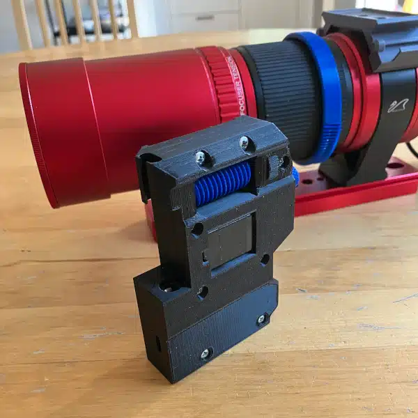
And there you go! The star tracker main housing assembly with the gears and main shaft in place. This thing is starting to look really sexy.
One thing I didn’t mention in the assembly above is that I did feed a couple of M5 screws through the base into the worm gear motor assembly. However, this is only temporary until I settle on how I want to incorporate this onto a mount.
Next Steps
With the main housing of the star tracker mostly complete, it’s time to move on to the next parts needed. To begin with, I’m going to work on the counterweight system. Now, this might seem like a weird next step. However, I want to test a system to lock onto the main shaft which I can incorporate into the camera mount extension.
Of course, I also need to print the top plate for the main housing to lock the combination gear into place with another small ball bearing. Then, of course, I need to design the camera mount extension – and I have some really cool ideas for that. At that point, I can probably begin testing Beta.
I’ll leave most of the electronics work until the end once I’m sure everything is working as designed.