![]()


Following the last test, I’m happy that I have a working 3D-printed star tracker. But how good is it really? The Lego Star Tracker was more or less a novelty build. But now I’m looking for a star tracker that I can use regularly to improve the quality of my deep-sky photos and improve my signal-to-noise ratio. So it’s important for me to understand the star tracker’s limits of operation. And I should know this before I get all fancy with tweaking and upgrading my design. The only problem that I have is that if I’m going to test the limits of my 3D-printed star tracker, I need to test it after achieving good polar alignment. And as you know, this has been a real pain in the backside for me.
First Things First
Before heading outside again, I need to fix one minor aspect of my design. I held off creating a box to house the Nano 33 IoT and the stepper motor driver so I could debug my code on the fly while testing. However, as I was pleasantly surprised to learn, I don’t have a need at the moment to modify my code as it appears to be working brilliantly. So now it’s time for me to build a box so I can drive the whole system from a USB powerbank. Hmmm, that reminds me – I should probably start charging my batteries and power supplies :).

I’m going to keep things extremely simple right now. I just want a couple of LEDs to indicate the status of the device. I’ll also incorporate a couple of switches to turn things on and off. I’m going to use 1 switch and 1 LED for main power and then 1 switch and 1 LED to turn the tracking on and off. I’ll need a couple of current limiting resistors for the LEDs and a pulldown resistor for the tracking switch. I also need a USB connector. I have all these things readily available in my electronics graveyard – just needed to whip out my soldering iron and start stripping things out. One thing I realized that I didn’t have was a bit of desoldering braid. This made things a little more difficult than they needed to be, but I managed.
It took me about 6 hours total to put everything together and rework my code to manage these additional parts. 4 hours of that time was just printing the box. As you can see, it’s not the prettiest implementation, but it works. So no snarky comments about my awful soldering skills – I seem to be very rusty.
Star Tracker Polar Alignment Test Strategy
I thought I was pretty much stuffed for options on trying to polar align the 3D printed star tracker with any semblance of accuracy. A while ago, I flirted with the option of using a webcam in a program called SharpCap to run a properly plate-solved polar alignment. However, I didn’t have any webcams available on hand that would allow me to modify the exposure times of the capture to actually begin to see the stars. I really wish there was a way to use my DSLR to resolve the polar alignment of my star tracker.
I would just mention that I am well aware that I can physically modify a camera to achieve the desired outcome. I’ll just reference exhibit A above as to how successful I think I can be performing surgery on very small boards given where my soldering skills are today…
As luck would have it, I stumbled across an article on CloudyNights that spoke of an ASCOM driver for DSLR cameras that in theory would allow me to use my DSLR in SmartCap. Why not? Mind you, using a DSLR for polar alignment isn’t the most optimal solution, but being in a bit of a pinch I was was willing to give it a go. I followed the instructions for the driver and didn’t have any problem installing it. And I was pleased to get it working in SharpCap without a hitch.
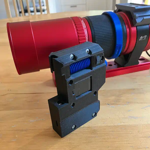
The last hurdle to overcome is building a little mount for the camera to align it with the axis of rotation of the star tracker. This can’t be a long-term solution but will be fine for testing purposes. Printed, mounted, ready!
Testing Polar Alignment with my DSLR in SharpCap
It was a bit chilly, but I managed to get everything set up to achieve polar alignment for the star tracker using my DSLR. I decided to use the 50mm lens to keep things light for now. I wasn’t sure if this was going to work given the large field of view. But I was relieved to see that SharpCap didn’t have any problems solving the photos that were coming from the camera.

SharpCap allows you to check your polar alignment in the free version of the program. However, if you want the program to help you actually achieve polar alignment, you’ll need to purchase the full version. After playing with the free version for the better part of an hour, I decided to go ahead and invest the ~$20 for a 1-year license. Money well spent as it will more than pay for itself in time saved messing around with polar alignment.
Needless to say, I was not disappointed with my investment. The program told me exactly how to adjust my star tracker mount to achieve polar alignment. All in all, I suppose it took me about 5 minutes to dial things in to achieve “Good” alignment.
Problems? Always!
While I was able to dial in my polar alignment, I had a facepalm epiphany. My elevation adjustment knob was working just fine to raise and lower the position of the star tracker. However, each tooth on involute gear represents a change in elevation of 20 degrees. So every rotation of my knob changes the elevation by 20 degrees.
The problem is that I’m trying to dial into minutes and seconds of offset to achieve polar alignment. 1 hour angle equals 15 degrees. Or 1 minute equals 0.25 degrees, and therefore 1 second equals 0.0042 degrees. There is no way for me to achieve that kind of precision with the knob adjustment strategy I’ve created. Hence, the facepalm. I should have thought about this beforehand. Don’t get me wrong, I can still work with what I’ve created, it’s just a bit of a patience tester when trying to dial things in.
I have some thoughts on how to fix this, but it won’t prevent me from testing so I’ll just crack on.
Photo Plan
Once I achieve “Good” alignment according to SharpCap, I’ll take a series of tracked photos with increasing exposure times. This will show me two things. First, how good my polar alignment is, and second, whether or not I have any gross mechanical issues with the tracker. I decided to shoot a number of 10-15 minute groupings at 30, 60, 120, 180, 240, and 300 seconds. I want to keep the ISO at 400 and will adjust my aperture as required to keep the photos from blowing out. We’re just about a full moon right now so there will be a ton of light pollution.
As you can see, there was a high degree of consistency in terms of the tracking quality between the exposure times. The picture below is a mosaic of 1000 pixel samples around Polaris and zoomed to 400%. The prominent star in the zoomed photos is HIP 113116 which is about 5 degrees away from Polaris. You can just begin to see star trails around 120 seconds but even at 300 seconds, the stars in the image remain sharp. At least sharper than anything I’ve tracked yet to date.
When shooting at 50mm, it’s clear to me that I would be able to take exposures of at least a few minutes without any issues.
Mind The Wobbliness
It’s vitally important to lock everything down tight once I set my alignment point. That’s one thing that I observed while I was setting up and playing with my alignment. I can see that I’ll need to redesign a couple of parts to remove a bit of wobbliness. This is true on both the horizontal and vertical stabilization components. As an interim solution, I’ll try to find a piece of rubber that I can use to offset the lack of friction and control.
I’m also seeing that I’m going to need to redesign the camera mount a bit if I’m going to be using SharpCap with the DSLR to polar align the star tracker. I’ve got a pan clamp that I’ll use to hold the camera. I’ll just need to get around to designing a bracket for that. I’m also going to remove the ball head from my tripod and mount the star tracker directly on the tripod base. This will lower the center of gravity which brings additional stability to the system.
Next Up
So that begs the question – what’s next? I think I’m going to get out tonight and repeat this experiment with my 18-135mm lens. I know now that this star tracker will work brilliantly with my 50mm lens, but what if I want to go longer? I’m going to mount my stock lens to see how things go with the weight and the alignment. Tune in next time to see how that goes.