Under Pressure
Well, a quick look at the forecast tells me I may have a window of opportunity tomorrow to actually try and test my DIY Lego Star Tracker Version 3. So the pressure is on!
I know what I need to do in order to prototype a new design that overcomes the issues I discovered with the last version. But what I hadn’t thought about yet is how I’m going to mount and align this device. So I’ve got some additional challenges to think about as well.
I’m hopeful that with this revision I’ll be able to set the design baseline moving forward. Clock’s Ticking!
Fixing Yesterday’s Issues
This is actually the easy part. I can fix the sheer weakness in my axle design by creating a square-ish axle using Technic bricks. I’ll simply plug the axle connector into this brick axle at the end where it meets the gear.
Next, the solution to fixing the friction issues is to use some kind of bearing mechanism. Well, Lego doesn’t have any ball bearings, but it does have wheels! I’ll create a pseudo bearing by resting the platform on a set of wheels which will greatly reduce the friction.
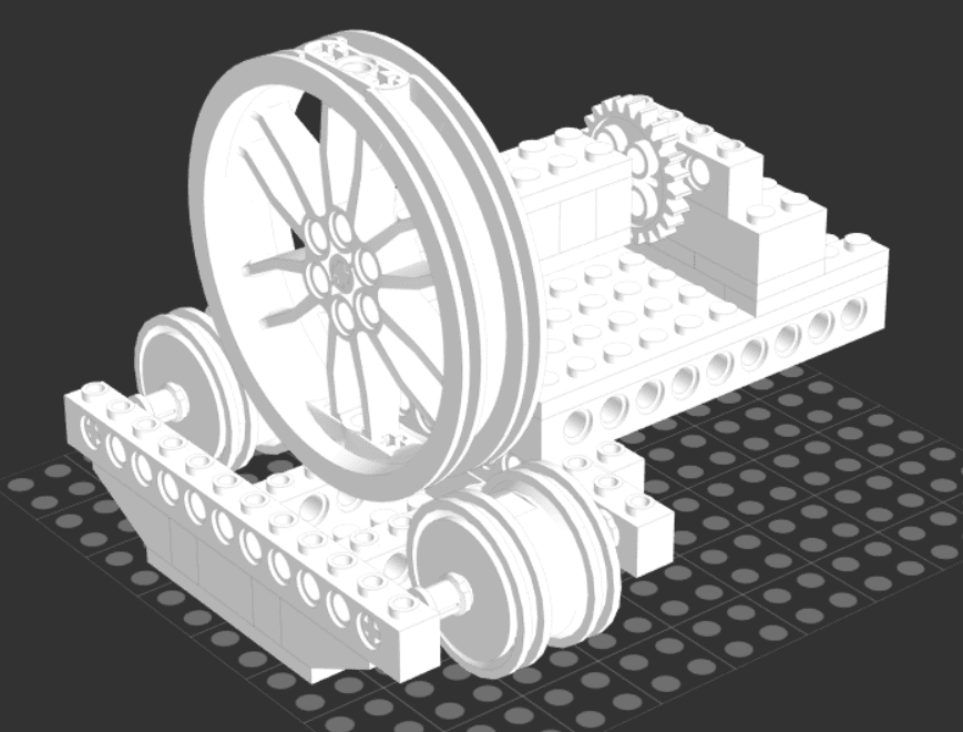
I can secure the camera mount by cutting a circular piece of wood and anchoring that to a large Lego wheel with screws to lock it all in place. Here’s what this part of the solution looks like now in Studio.

Unfortunately, I didn’t finish creating the whole device in Studio because that required time I didn’t have. This was good enough to give me a rough idea of what I wanted to create. Now I just needed to build it with bricks.
Putting Version 3 Together
By now, I know what I’m doing. So building this version of the tracker didn’t take me all that long. I spent more time cutting a wooden disk and securing that to the Legos than I did putting the actual Lego structure together.
I cut a small piece of 1/4″-20 threaded rod about an inch long and simply threaded that through a center-cut hole that was a wee bit too small. This was by design as I seem to be all out of standard nuts living in the middle of Europe. Turned out that a 6mm drill hole is about the perfect size to thread a 1/4″-20 rod through on a piece of wood to get a solid fit.
On the end of the rod, I added a Manfrotto Mini Ball Head mount that I picked up for about $12. For what it’s worth, the plywood I am using cost about $7. Obviously, Legos aren’t cheap, but it’s what I have without having to spend any additional money. Remember, I have four boys who by now have racked up a combined 54 years’ worth of birthday presents. 🙂
While holding my breath I began to load test this contraption and … it seems to be working fine. OK, now the real test … will it work if I attach my camera? Amazingly, YES! Ok, don’t get as excited as me. It’s totally clunky. I already see there are a host of new issues that I’m going to have to deal with. The big question is, do I think I can actually use this to try and take some tracked photos?
Yes. Yes I do.
Right, Now What?
OK, I need a way to mount this and get it polar aligned. Immediately, I can eliminate any solution to mount this on my tripod. First, I don’t have the right bolts. Second, as I said, it’s a bit clunky and I’d spend more time worrying about knocking it over or even off!
I think the best way forward, for now, is to build a fixed base where I can angle the device up at 50 degrees. What’s the easiest and most stable way to do this?
I can use Technic bricks and lift arms to secure it close enough to the right elevation. OK, fair admission, I had to play around with the numbers a bit to find a combination of holes that would yield a 50 degree-ish angle of elevation (a constant based on my latitude). You can calculate this using maths and counting holes or alternatively, you could just get a protractor and eyeball it. Either way, it’s not going to be spot on, but I accept that for now.
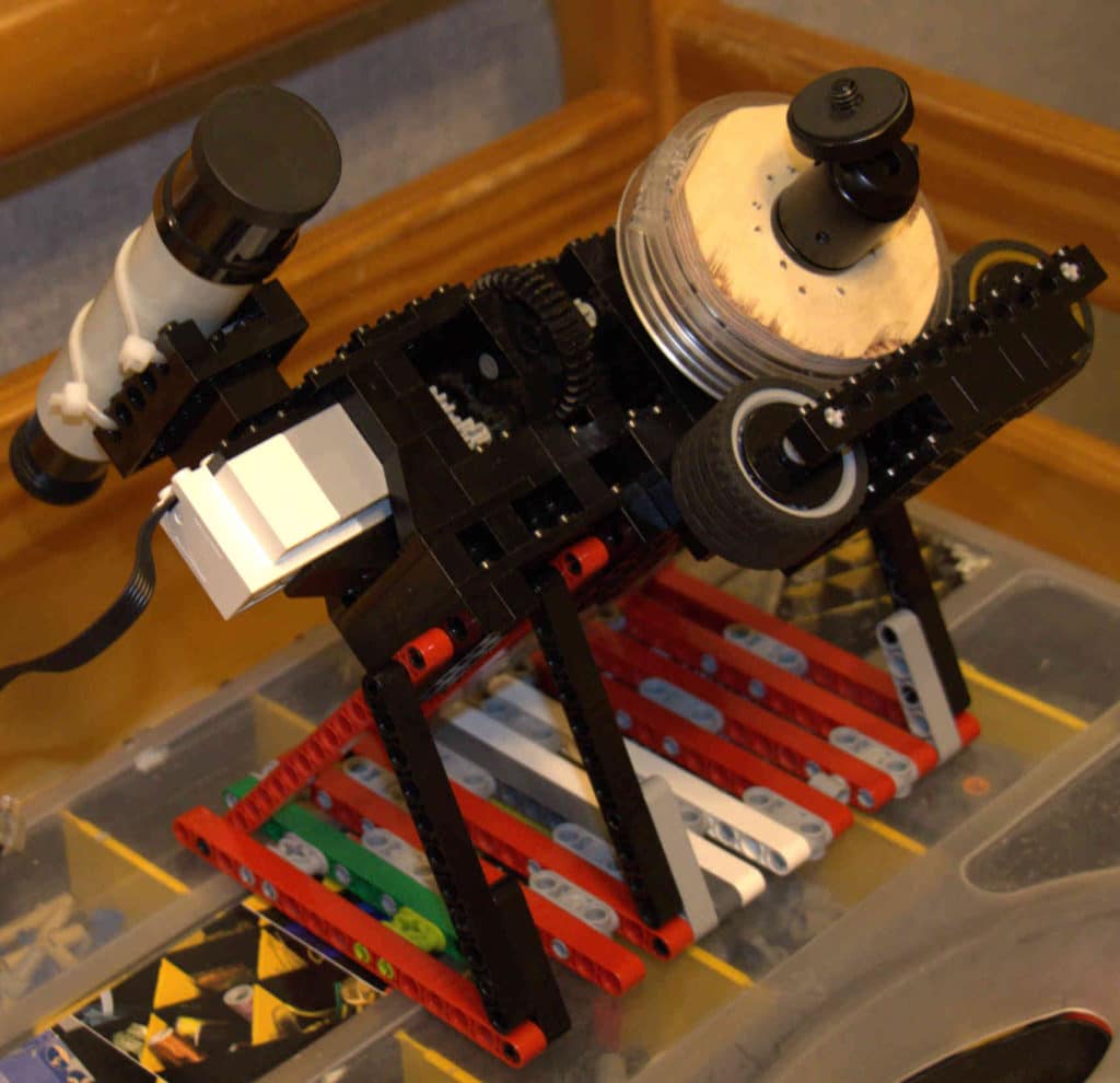
So that’s what I did, I just snapped a whole bunch of lift arms together at the right dimensions and that gave me a flat enough, and stable enough platform to mount my camera on at the right altitude angle of the pole – well, within a reasonable amount for a first test. Here’s a snap of the finished product.

I also grabbed a finder scope that I sniped from one of my son’s kit telescopes that he got for his birthday years ago. I simply zip-tied this to a few Lego bricks so I can attach it to the rig. This will make it easier for me to line up the pole (close to Polaris) when the time comes.
Now all I had to do was level up a table in my backyard to place this device on when the time comes. That turned out to be a lot more frustrating than I expected to be honest, but I finally got it close enough.
Now I wait…
