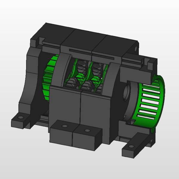
Time to get into some of the things you want to see with the Star Tracker Gamma. 27 out of the 45 printed pieces in Gamma can be found in the gear train. Taken together, this is the most complex and complicated aspect of the tracker. Therefore it makes the most sense to tackle this whole assembly in one single post. So, let’s get to talking about the planetary gear drive, or the guts of the Star Tracker Gamma.
Planetary Gearboxes Are Cool
I’m going to assume that you know a little bit about planetary gearboxes in this post. If you don’t, there are plenty of sites online that can walk you through the basics of how planetary gears work.
Design Considerations
I chose to go with a planetary gearbox design for three primary reasons. First, these guys pack a lot of punch in a very small area. You can easily generate 4:1 or better gear reductions with planetary gears that take up a significantly smaller area than can be achieved with involute gears. Second, you can ramp up the torque in your gear train very effectively. And finally, you can stack planetary gears by having the carrier arm drive the sun gear of the following planetary stage. This improves the precision and control of movement. And that is basically what I am doing with the planetary gear drive in Star Tracker Gamma.
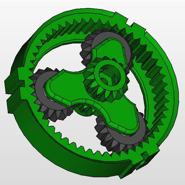
Using three planets, the critical thing to remember is that in order for the gears to all mesh properly, you need to ensure that the sum of the number of teeth in the ring gear plus the number of teeth in the sun gear, when divided by the number of planets, yields a whole number. For Gamma, the equation would look like this: (51 + 15)/3 = 22. 22 is a whole number so I know my gears will mesh smoothly.
Now to figure out the configuration of my gears, I used an online planetary gear generator. I wanted the highest reduction for a reasonably sized ring gear. I found that using a ring of 51 teeth, a planet of 18 teeth, and a sun of 15 teeth would yield a 4.4:1 reduction for each stage of a 3-stage design (132.5:1 overall).
Torque Improvement
The torque improvement of using this planetary gear drive is pretty straightforward to calculate. I know that the torque of the motor during movement is 34.3mN*m. That’s way too small to expect results when loading 2kgs of gear onto Gamma. I’d have to just about perfectly balance the load. So the cool thing here is that the gear reduction of this drive ends up being the torque multiplier. So at 132.5:1, the torque I’ll get with this drive is about 4.5N*m. With reasonable balancing during operation, this will be more than enough to handle my camera load.
Movement Precision
I’ve already mentioned a few times that the overall gear reduction for Gamma is 132.5:1. When coupled with the fact that the stepper motor I’m using can step 4076 times per revolution, this gives me a lot of control over my camera movement during operation. I’m going to go over the actual calculations in another post in the Gamma Deep Dive series, but I thought I’d mention here that my goal with the reduction is simply to ensure that I can execute several move commands per second. In theory, this means that I can probably safely use any focal-length lens I want on the tracker without having to worry about star trails.
As of right now, I’m not looking to invest in a telescope so I’m not designing Gamma for that purpose. I’m sure I’d probably look to change some things about Gamma if my imaging gear was different.
Printing the Gamma Planetary Gear Drive
Gamma uses a 3-stage planetary gear stack that is held in place using brackets. The stepper motor used in this project attaches to the gear stack brackets via a motor bracket. I also printed a couple of grills that would protect the gears and provide a little ventilation for the motor to dissipate heat. And darn it, they just look cool. Ok, here are some of the details behind the printing.
Planetary Gears
It’s one thing to have a design worked out on paper. It’s another thing altogether to print a working solution. Honestly, I must have printed about 100 gears trying to get things working right with my printer. I turned the corner though when I modified my printer a bit which gave me much more precision in printing the gears.
As if I wasn’t trying to make it hard enough for myself, I used a very aggressive gear module of 0.8 for my gears. In order to do this, I found that I needed to increase the clearance of each gear to 0.35mm, increase the backlash to 0.1mm, and reduce the head length by 0.1mm to get everything working smoothly. This was accomplished by trial and error – hence all the printed gears…
It was important that all the gears printed well. So I slowed down my print speeds to a crawl and set my layer height to my printer’s minimum. I also printed directly on my glass bed surface (ie. no raft) and my gear design did not require supports.
The “next stage” sun gear is attached to the carrier arm via a hex inset plus a washer and M3 screw to ensure the gears all stay stable and properly oriented. A dab of crazy glue here and there adds a little extra security and peace of mind. Each planet receives a 3mm x 7mm x 3mm press-fit bearing mounted on a carrier arm post. This was all designed to hold everything snug.
Brackets and Grills
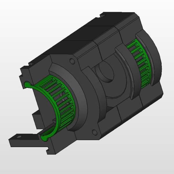
OK, nothing really too fancy to see here. I used the standard print settings on my Adventurer 3 to print the brackets and the grills. You can see the Freecad rendering of these components below. There are a total of 4 brackets and 2 grills.
I printed all of these parts using rafts. The reason for this is that the brackets are so large that the heat distribution from my print bed was very uneven. This resulted in a little warping of the final pieces which for obvious reasons was undesirable. When printing with the rafts, there were no issues with warping whatsoever. However, I did have to wrestle with the rafts a little bit after printing, but nothing a putty knife couldn’t easily manage.
Fully Assembled Views
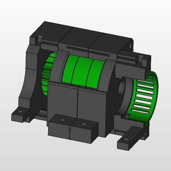
Finally, I wanted to show the FreeCAD rendering of the fully assembled Gamma planetary gear drive. The image on the left shows all the printed pieces in the Gamma planetary gear drive. The image on the right is the same view without the ring gears so you can see how the planetary gears stack.
| 
|
The beauty of this design is how it plugs into the main housing of the Gamma Star Tracker. This allows me to really lock everything in place and means I can swap out pieces as needed in the future.
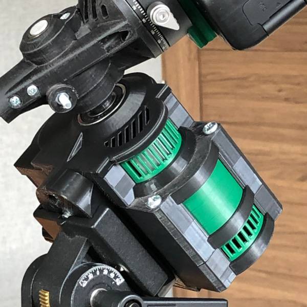
One final note here would be that when I assembled this part of the project I used a liberal amount of silicone grease on the planetary gears. I’m not worried at all about heat generation with this project but rather about the smoothness of movement. The grease is going to tamp down on any motion effects due to slight variations in the printing of the gears.
Parts List
I thought I’d include a parts inventory so you can see what the Gamma planetary gear drive requires along with the approximate part costs. I’m not going to price out the plastic because it’s pretty cheap at $20/kg and Gamma used far less than that overall.
You’ll notice that the bearings account for the majority of the cost of this stage of the project. Yeah, I bought better bearings and paid a premium for them. I’m fine with that.
| Part | Qty | Cost |
|---|---|---|
| Planet Gears | 9 | |
| Ring Gears | 3 | |
| Carrier Arms | 3 | |
| Mid-Sun Gears | 2 | |
| Sun Drive Gear | 1 | |
| Motor Bracket | 1 | |
| Front Ring Bracket | 1 | |
| Mid Ring Bracket | 1 | |
| End Ring Bracket | 1 | |
| Motor Grill | 1 | |
| Gear Grill | 1 | |
| Output Gear Seat | 1 | |
| Output Gear | 1 | |
| Output Gear Cap | 1 | |
| 3mm x 7mm x 3mm Bearings | 9 | $15.00 |
| 10mm x 15mm x 4mm Bearings | 2 | $15.00 |
| M4 x 60mm Screws | 2 | $0.25 |
| M3 x 10mm Screws | 2 | $0.25 |
| 28BYJ-48 Stepper Motor | 1 | $5.00 |
| Totals | 43 | $35.50 |
Final Comments
Well, that’s the Gamma planetary gear drive that I’m currently using. Next, I’ll cover the electronics box and the main housing. After that, I’ll write a little bit about the camera mount. You’ll be happy to hear I’ve reworked the entire camera mount per my stated goals and I’m just waiting to get it outside for some testing. But that might take a while as the weather has been downright poor lately. We’ll see.
I’ll add the FreeCAD files shown above to the 3D printed page shortly. I’m not going to put this design up on Thingiverse as I feel it’s just a bit too complex to be useful for much else than inspiration.
