I won’t even try to pretend that this post is going to be all slick and stylish. If you’ve been reading along, you’ll know I try to keep things simple. What you will find here though is Part 1 of a series of posts about the technical details behind the Gamma Star Tracker. It is not my intention that you’ll look to duplicate my work, but rather that you’ll get some ideas for your own projects. There’s a lot to talk about with Gamma but I thought I’d start with an overview of the Arduino code and the electronics behind Star Tracker Gamma.
Gamma Arduino Code
Originally, I wanted to post the electronics of the Gamma Star Tracker next to the Arduino code that controls it. However, I think this will be a bit confusing. Therefore, I’m going to start this post by inserting the entirety of the Arduino code in a PDF file below. I commented on most of the code and it’s all rather intuitive if you’re familiar with the Arduino platform. If anything is unclear, you can always drop me an email or post a comment and I’ll respond.
GammaArduinoCodeMaybe one thing I’ll comment on here that you might not find obvious. Since I’m running everything using non-blocking commands, I don’t want to execute tons of code during every iteration if nothing is changing. Therefore, I have an initialization subroutine that sets a flag to let me know if I’ve already set the current device state up. Then I can simply test the flag to see if I need to change the switch state or the led state without explicitly running these commands every time.
Gamma Switches
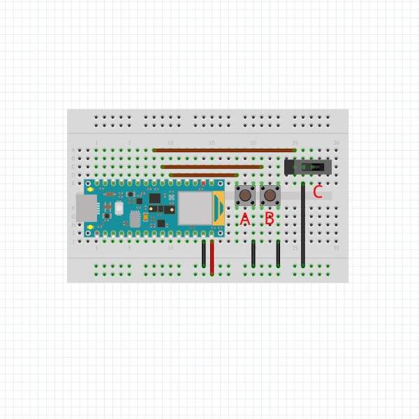
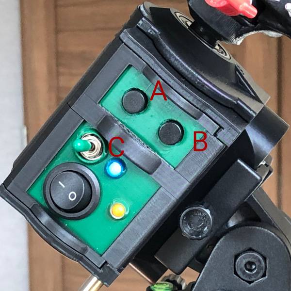
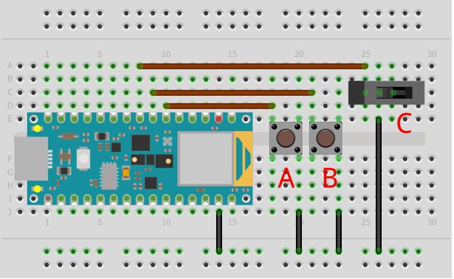
Star Tracker Gamma has 3 switches that drive motor actions. Switch A slews the camera mount counter-clockwise. while Switch B slews the camera mount clockwise. Switch C puts the camera mount in tracking mode. It’s important to note that Switch A and B will only rotate the camera mount if Switch C is off.

| 
|
Gamma is designed to run in non-blocking mode. In other words, I’m not using software delays to control the tracking code’s timing, but rather the hardware timer to manage the timing. This delivers the most accurate timing which is important if I want to ensure that Gamma is rotating at the right speed for tracking.
In order to reduce the amount of circuitry in Gamma, I decided to use the internal pull-up resistors available on the Arduino Nano 33 BLE Sense chip. Fortunately, there is a library named ezButton that manages the chip settings and it also runs non-blocking. It was exactly what I needed and greatly simplified my code as it also handles debouncing the buttons.
Gamma LEDs
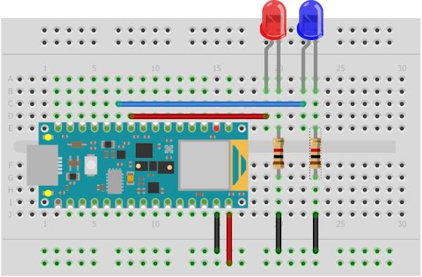
There’s nothing tricky about wiring up the LEDs. Just make sure you know which terminal is the anode and which is the cathode. I’m using 1k resistors to keep the current as minimal as possible. At 3.3V, this means I’ll have 3.3mA through the LED. After your eyes adjust to the darkness, these suckers are almost blinding. So you might want to consider even going without LEDs.

In the Gamma Arduino code, the red LED will be set to on when the tracker is powered on. The blue LED will be on continuously while tracking and will pulse when slewing. If no switches are in an on state, the blue LED will be off.
Gamma Stepper Driver and Motor
Gamma uses a 24BJY-48 stepper motor with a ULN2003 driver. The driver boards come in all kinds of different flavors and I just found one that was compact and suitable for my design. Point is, you don’t need the exact same parts I’m using.
I chose the 24BJY-48 stepper for a couple of reasons. First, it’s small. Second, it is internally geared which gives me 4096 steps per revolution (or 4076 measured). I can take advantage of that to achieve the precision I need to drive the output accurately. This motor has very little torque though, so it’s absolutely necessary to gear this down further to be usable for this application. With a three-stage planetary gear stack, torque won’t be an issue for my design. But this little guy will cook if you leave the coils energized. So I’m only leaving the current on the coils for the first 1/3 of the waiting period. Will I have a little backlash? Of course. But if Gamma is even close to reasonably balanced, it’ll be nearly impossible to backdrive.

I’m controlling all of this using a very functional library named CheapStepper. More information about this library is found on GitHub.
Gamma Power
The only thing left to talk about from a circuitry perspective is my power source. I designed Gamma to run via an external powerbank that connects via a micro USB port. I chose this option because the stepper motor driver needs upwards of 2.5A to operate smoothly at 5V. In the design, I have a power switch that breaks the power from the USB port to both the Arduino Nano 33 BLE Sense chip and the stepper motor driver board. And that’s really all there is to know about the power supply.
Next on Tap
I can’t guarantee that this will be my next post, but in Part 2 of the Gamma Deep Dive, I’ll dive into the 3D-printed parts that I created. Spoiler alert – Gamma has almost 50 printed pieces in the design. So it’s going to take me a while to document things. But apart from the electronics and code, I’m sure that’s what you’re waiting to see when reviewing Star Tracker Gamma.
Finally, it’s worth noting that I’m already working through some of the goals I documented in my last post. Particularly, I’m working on a new camera mount design as those modifications are going to be necessary to get the most out of Gamma this winter. Anyway, hope you found this post interesting – ping me if you have any questions.
