![]()


I enjoyed a couple of nice nights out taking pictures and spending some time with one of my sons. Was I successful? Well in a word, no. But I learned an awful lot and it was great just being outside. I’ll write more about this past weekend soon. But in the meantime, I also got some work done on the electronics for the 3D-printed star tracker. And as promised, I’ve updated the Arduino Nano 33 IoT bracket that sits on the ULN2003A driver board. So I thought I’d give you a quick update on this exercise.
Modifications Made

I made a number of modifications to Nano 33 IoT bracket. The first and biggest change was just to allow the micro-controller to plug down into the bracket, rather than seat the chip upside down. This change simplifies the design of the bracket significantly and reduces the overall profile height of the electronics.
I also decided to extend the access hole underneath the bracket to extend beyond the front post to allow additional wire access.
Next, I created a second row of holes to feed the wires into at a 45-degree angle. This will keep the wires in place a lot better than the cutout approach I used on the first iteration.
I also decided to allow the post holes to pass through the whole bracket. This is also a trick to give me a little more control over securing the wires to make good contact with the header posts.
And finally, I shortened the width of the bracket. There was really no need to have it as long as it was and it just saves a little plastic.
Wiring Solution For Connecting to the Driver Board
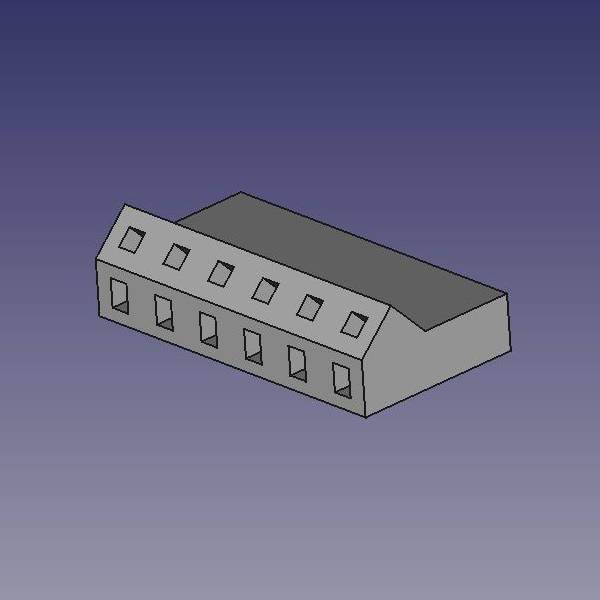
Similarly, I created a cap for the header pins on the ULN2003A using the same principles I used for the bracket. There’s not much to say about this, but here is a FreeCad image of this header cap.
What I found through testing this wiring solution is that the wires hold best when you use a 24-gauge wire. Well, I’m all out. So I took a quick trip to the hardware store thinking this would be easy to find. I was wrong. Nothing. So I thought about this for a minute and remembered that Cat 5 ethernet cable is solid 24-gauge wire. Brilliant. That’ll certainly do. It’ll be a little stiff when I’m running the wires. But I’m not going to be running tons of wire at this point so I’m fine with this. Plus, it’s cheap! Double plus – 8 wires of different colors!
Minor Update – Did I mention that the Cat 5 wires were going to be stiff? Wow, my fingertips are absolutely raw from trying to run the wires from the board to the bracket. Oh well, I’ve got it hooked up and a quick power test proves that it’s all running fine. I may have a think about this though. It might be possible for me to just thread the wire through the holes at an offset to the header pin shaft and allow the header pins to just cut through to make contact. We’ll see.
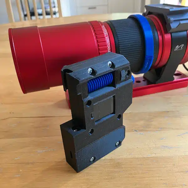
Final Product
I’ll be short and sweet to close this post. Below is a picture of the bracket assembled and wired for a quick test.