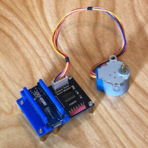
Good news! We might actually get a couple of clear nights over the next couple of days which means I’ll be in the field soon. Whoo-hoo! I was holding out hope the skies would open up tonight, but it looks like I’ll just need to wait. So, while I let my excitement build, I can turn my attention to my other project – the 3D printed star tracker. I’ve got my electronics and now I can get to planning what I want to do. Basically, I’ll start by just playing around with things before building an Arduino Nano 33 IoT bracket for development and testing purposes.
First Take on the Board, the Driver, and the Motor
Arduino Nano 33 IoT
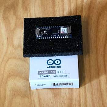
I’m familiar with Arduino boards so I’m not expecting things to be too difficult with the Arduino Nano 33 IoT board. This is, however, my first Nano form factor board, so I’m looking forward to testing it out. I had a chance to check out the Inertial Measurement Unit (IMU) and was impressed. The Nano 33 IoT has a 6 axis IMU and I’m kind of kicking myself now that I didn’t opt for the Nano 33 BLE which has a 9 axis IMU. Yeah – I’m thinking super easy polar alignment *smile*. I’m going to design this system to be modular so I’ll be able to pick up a Nano 33 BLE in the future and just swap it out. But I’m a long way off from getting to that point.
There is one thing that I’m a little unsure about at the moment. I ordered this board with headers but I really didn’t give much thought to how I’m going to wire this all up for the final project. I always assumed that I’d use this board with the headers attached as my breadboard development module and I’d simply purchase another chip without the headers for the final system. But I’ve been doing a little thinking after evaluating the stepper motor and I may simply go with the board with headers after all. I’ll explain further in a bit.
Stepper Motor and Board
Mouser Electronics sells a package from OSEPP that includes a 28BYJ-48 4-phase stepper motor that is mounted to a ULN2003A driver board. Again, I want to keep things simple at the start so this kind of package deal was just what I was looking for.
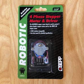
I did fire up the motor using the Nano 33 IoT and a simple sketch using the cheapstepper.h library. There was considerably more torque on this motor than I was expecting. And that’s a good thing. I also took the liberty to poke into the full library page and was surprised to see that this simple program has some nice features. You can code the operation of the stepper using blocking and non-blocking commands. You can also micro-step this device. So everything is looking alright so far.
But… I unmounted the motor and was kind of disappointed to see how large this board is. Space is going to come at a premium in this project and a board this big is going to be a problem. I’m going to need to think long and hard about how to manage this.
When Boards Give You Lemons, Make Lemonade
OK, that section title is kind of corny – but that’s me sometimes… And I may have found a solution to my driver board size problem. Of course, I know I can buy the same driver mounted on a smaller board, but where’s the fun in that? I’ve got this 3D printer, so why not print a bracket for the Nano 33 IoT that will screw down onto the ULN2003A driver board? Ummm, yeah!
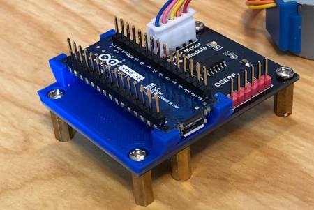
Now, I’ll show you what I’ve done, but as I’m writing this, I’ve already changed my mind on the approach. But basically, I’m going to print a small base bracket that lines up with the screw holes in the driver board that has printed standoffs to mount the Nano 33 IoT. Then I’ll mount the board upside down to expose the header pins and just connect my circuits from there.
I think tomorrow, I’m going to change the Nano 33 IoT bracket to just accept the header pins. Then I can employ a kind of solderless solution for wiring. I figured this out after printing a couple of header pin slips for the upward-facing header pins. There are a couple of other advantages to this approach. First, it will lower the profile of the Nano 33 IoT board. And second, I’ll be able to forego screwing the board down as it will be held firmly in place by friction.
Printing a Nano 33 IoT Bracket for the ULN2003A Driver Board
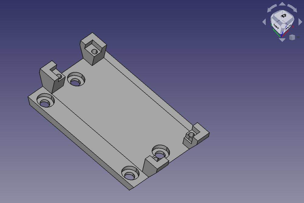
Below is the bracket that I designed in FreeCAD. You’ll see it’s rather simple but I did have to fiddle around with the measurements to get everything right. As it turns out, the Nano 33 IoT board was a little bit bigger than the datasheet indicated. I double and triple-checked this. I suppose this was just a manufacturing process anomaly, but my board was almost 1mm longer than the datasheet said it should be. Not a problem, just a “feature” to design around. By the way, this won’t be a problem at all when I redesign the bracket.
And here’s a picture of the finished print with the Nano 33 IoT mounted. Now I’m going to need to do something about all those little daggers sticking up…
Header Slips for Wiring
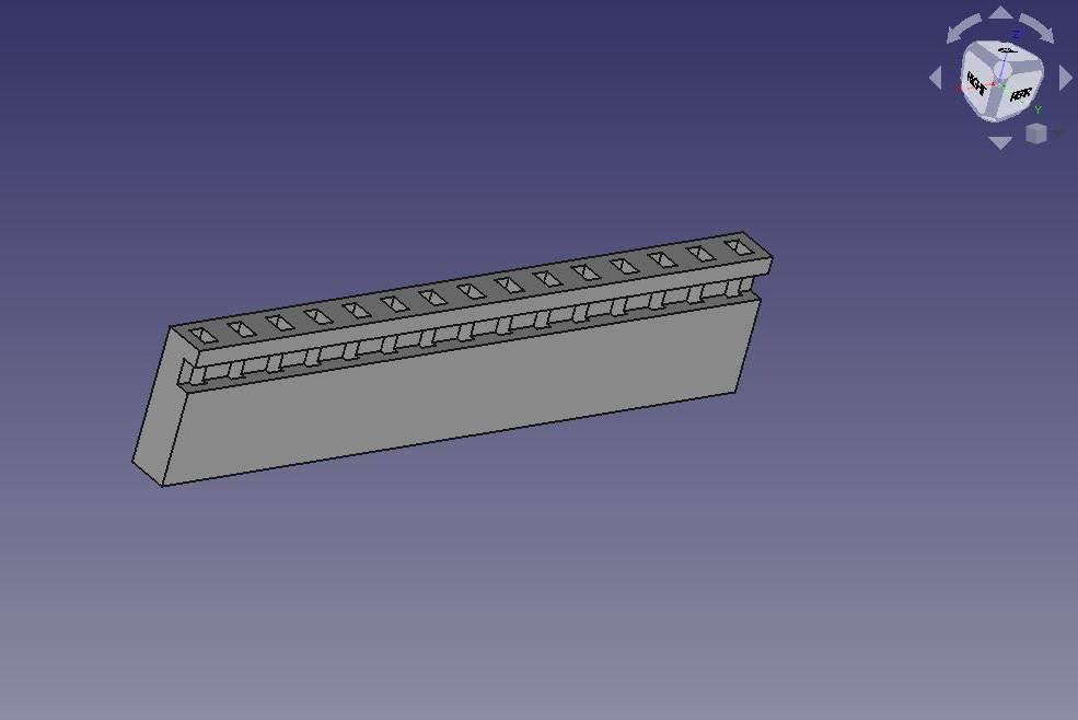
After seeing the results of the printed bracket, I’m feeling a bit cocky. The next thing I want to do is print some slips that will fit over header pins. I figured if I oversized the holes just a little bit, I can thread a wire into the channel that will make good contact and lock into place. To accomplish this, I just carved an opening at the bottom of the slip to accept wires. Below is the FreeCAD draft of the slips.
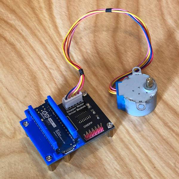
I’m a bit surprised by how well this works. I need to get some different wire, maybe some 24 or 23 gague. But this is going to work nicely. Especially when I redesign the base as discussed above. Anyway, here’s a picture of the slips on the Nano 33 IoT header pins when seated in the bracket.
What’s Next?
I’m going to be printing the new bracket and while that’s happening I’ll work on the power supply mechanism. I’ll go part snatching in my electronics graveyard in my garage. Yay, I’ll be able to rev up my soldering iron. I’m going to need a micro-USB port and a switch or two. Oh, I forgot to mention, the powerbank powers the Nano 33 IoT and the driver board perfectly. No issues whatsoever as expected.
OK, that’s all for now. I’ll post a short update when the new bracket is done. But hopefully, my time over the next couple of nights will be spent imaging!
