I really do appreciate it when people reach out to ask questions. In fact, more than appreciation, I find it motivating. So for the handful of folks asking about the Samyang 135mm focuser, I’m happy to inform you that it is almost completed. No, really, I mean it this time. True to my word at the end of my last post, I’ve cycled back on this. And I want to thank you because this demand is what’s pushing me over the finish line on this project. So, if the DPD guy pays me a visit, this project will wrap up by this time next week. And just to make it interesting, I find myself on the clock as there are clear skies in the forecast starting in a couple of days! So let me get you caught up on the latest.
So Many Decisions
Besides my natural desire to procrastinate, I’ve really struggled with a number of design requirements. I think about what I want to get out of the device when I’m using it in the field. And of course, there are always going to be tradeoffs. This is really what has shelved the development of the focuser over the past few months. I find when I’m really wrestling with something that it’s best to simply put it away for a little while and come back to it in the future. And the future is now, so let’s get rolling.
To Tether or Not To Tether, That is the Question
I’ve been all over the map in my thinking on how to power the focuser. There is a big part of me that wants to design this to run off of rechargeable batteries to maximize the portability of the solution. Not to mention, I’m not particularly thrilled to add yet another cable to my rig. That said, I’m going to wuss out for now and externally power version 1 of this device. This is going to allow me to work out all the kinks and experiment a little more. This decision results in a slimmer and sleeker overall design.
Absolute Positioning?
Another topic I’ve wrestled with is whether or not I want to support the absolute positioning of the Samyang 135mm focuser. The thinking is that I could add an encoder or an analog measurement through a potentiometer to track the step position of the focuser against some baseline. At first, I was concerned about what would happen if I rotated the focuser against the Samyang 135mm’s focus stop. Would I damage the lens? Will I burn out my motor?
I’m using the 28BYJ-48 5V stepper motor with an in-traction torque of 32mN*m. That isn’t going to break anything as you can easily stall these motors by hand. So I’m not worried about damaging the lens if I butt up against the focus stop. Now, by way of reminder, I’m using these stepper motors because they are dirt cheap and easy to get and use. But I would probably think long and hard about what happens around the focus stop if I was using a beefier stepper motor. Limit switch maybe?
So how about the motor? Well, stepper motors draw their maximum current when they’re holding their position (ie. – not actively moving). As such, I’m not at all concerned about the ramifications of stalling the motor out. Besides, you’re going to notice when you’ve hit the focus stop and the motor is stalling. I wouldn’t want to hold the motor in a stalled state for very long. But that is out of concern for the internal gearing of the 28BYJ-48 stepper motor, not the motor itself.
The verdict, therefore, is that I’m not going to worry about adding additional parts and code complexity to achieve absolute positioning for this design.
You’re Not Going to Like the Backlash
Fair warning, it’s going to be downright awful. Testing over the past couple of days has revealed that I’m seeing about 4 degrees of backlash with the Samyang 135mm focuser. At first, I thought my gears were rubbish which surprised me. I’ve gotten rather full of myself in how well I’ve been printing gears lately after literally hundreds of failed prints. The problem is with gears, but not my gears…
Personally, I want a direct drive solution. That obviously comes with the understanding that there will be slack in the gear train that needs to be managed. This brings me back to my little buddy – the 28BYJ-48 stepper motor. On the motor that I’m using, there is a whopping 3 degrees of backlash in the internal gear system. OK, so you get what you pay for. But that means my gears only introduce another degree of backlash. Not great, but I can live with that. Now for those of you screaming to use a belt drive here… Why? If the motor I’m using is responsible for 75% of my backlash, that won’t get any better using a belt.
So my choices are to either upgrade the motor or manage the backlash in code. Ummm… I’ll take the manage in code route.
About That Code
OK, I have good news and bad news. The good news is that I’ve posted the Arduino and Windows Forms App code on GitHub. You can find the latest version of the project here. Please note that both the WFA and Arduino code is very beta at the moment. I plan on cleaning it up quite a bit over the coming week(s).
Now the bad news… The latest version of the code doesn’t have any hooks to manage the backlash issue that I previously mentioned. So in the coming days, I’ll be making an update to allow for a user to input a step value for the device backlash and a state variable to track the movement direction. If the user changes the movement direction of the focuser, the backlash steps will be added to the base move command.
And just so nobody finds themselves disillusioned. Just because I know how to program, doesn’t mean I’m a good programmer. When it comes to C#, I’m a total hack and this was the first C# program that I ever wrote. So please keep all the “Your code sucks” comments to yourself :). Now if you wanted to cross swords on PERL – well we could have a discussion about that…
Should I Take the PCB Plunge?
I mean honestly, there’s just something sexy about a well-designed printed circuit board. And wouldn’t I just love to add that to my list of skills for astrophotography and 3d-printed applications? Yes, I would … But not right now. I really want to share my work and design and something like a custom PCB would put this out of reach for some folks. So I’m going to go a little old school here so that people can follow along.
I considered building this out on a prototype board. But I can’t order boards in the size that I’d like. Nor do I want to get into cutting those things. Seriously, don’t do it unless you know what you’re doing – your lungs will thank you. So my solution is going to be a bit hybrid.
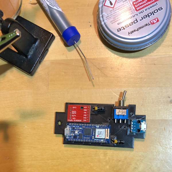
I’m going to 3d-print a prototype board and wire wrap the design. The DPD guy I mentioned earlier? He’ll be delivering a Radio Shack wire wrap tool. Old school and retro – love it. But back on point, I really don’t want to solder a $30 Nano 33 IoT chip in place for this project. I’m just not a big fan of permanence. Wire wrapping is a much less destructive approach. Now, there will be a little bit of soldering required which will take place away from the PLA+ plastic, but only for the switch, LED, and the bypass and decoupling circuitry (I know my solution here is not optimal, but it doesn’t need to be). Hopefully, if you’re as allergic to soldering as I am, you’ll find my approach a suitable middle ground. Or, of course, solder away… Enough, talk, here’s a peek.

Samyang 135mm Focuser 3D-Printed Parts
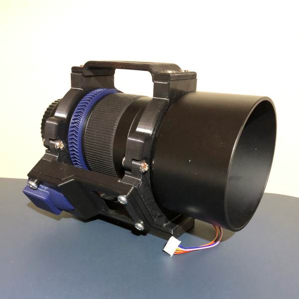
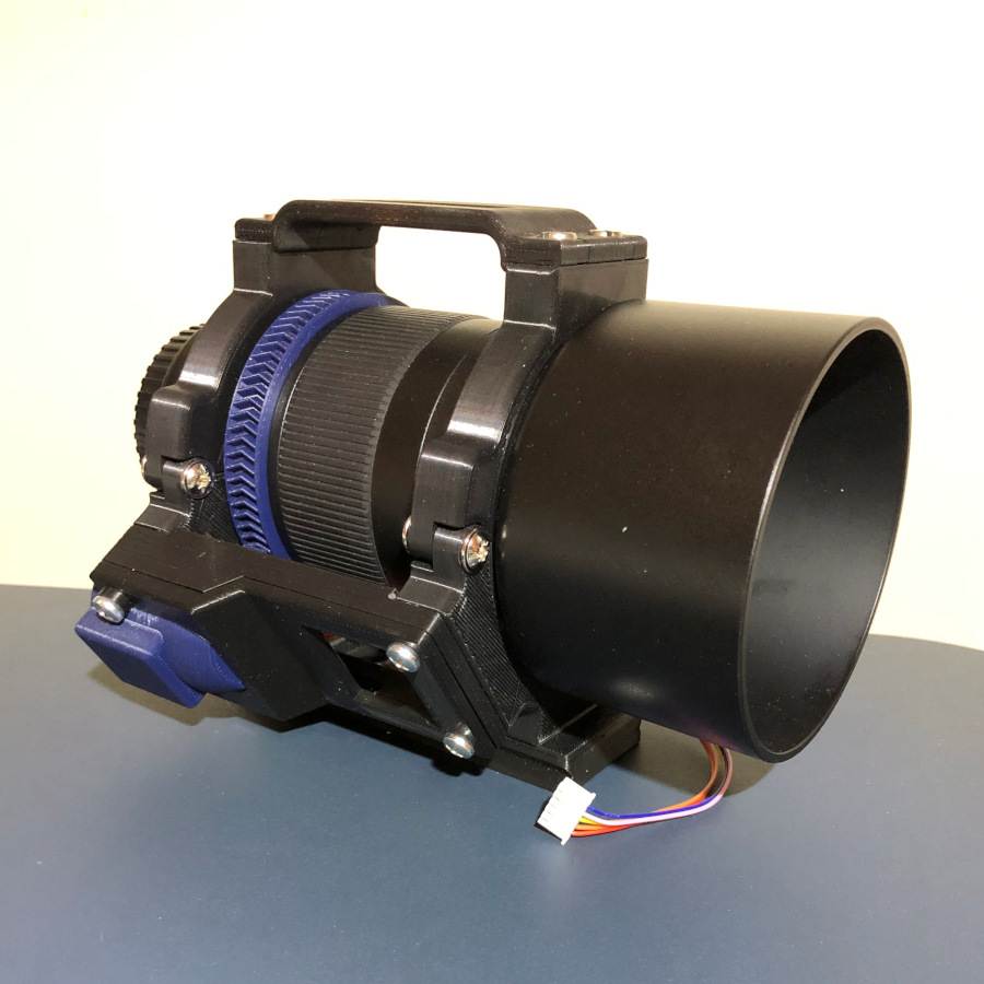
As I write, my 3d printer is cranking out the electronics box for the finished focuser design. See, I wasn’t lying when I said it’s really close! All told, there will be 9 3d-printed parts for the Samyang 135mm Focuser. There are 2 gears: a drive gear and an external ring gear that attaches to the focuser. Next, there are 4 printed parts for the motor case. Truth be told, 3 printed parts would suffice, but I wanted to add a splash of color to my design so the colored part required an additional print. Finally, there are 3 printed parts for the electronics: one for the case, one for the prototype board, and a lid.
Obviously, the electronics box isn’t completed and wired yet, but here is a quick peek at the collar with the motor housing attached. I am really looking forward to showing you the final version, fully assembled.

Alright, that’s all I have for right now. Hopefully, the forecast is correct and I’ll have some clear skies to actually get out and image again next week. Stay tuned.
