![]()


The DPD guy made my Monday when he showed up to deliver the wire wrap tool I had ordered. Now I had everything I needed to finish wiring up the initial release of the Samyang 135mm Lens Focuser. I wanted to savor the finishing touches of this project, however, the wrapping tool made quick work of the final stage of this journey. It was all over in about 15 minutes. Bittersweet. The good news is that the focuser is now in a state where I can begin to share the design and code details.
3d-Print Files on Thingiverse
You will find a lot of information about the Samyang 135mm Lens Focuser on the Thingiverse site and I’m not going to rehash all that information here. The focuser is an add-on to the Samyang 135mm Lens Collar design also hosted on Thingiverse. You can find both at the following links respectively:
Samyang 135mm Lens Collar
Samyang 135mm Lens Focuser
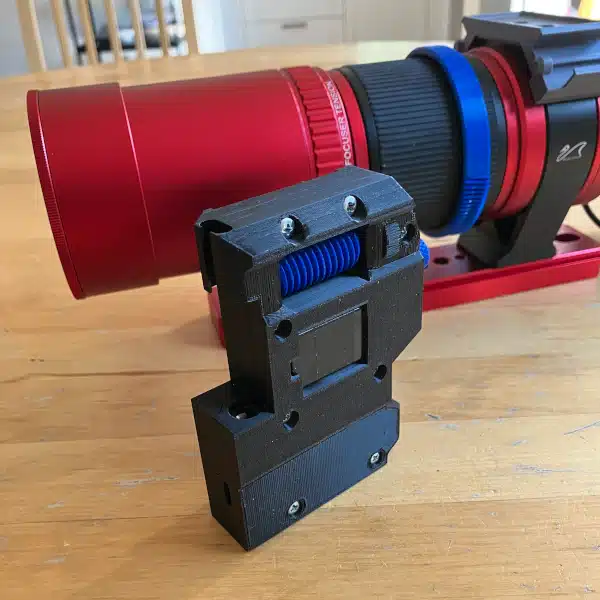
The focuser has nine 3d-printed parts: (2) gears, (4) motor mount elements, and (3) electronic housing elements. At a minimum, you’ll need to download and print the gears and motor mount elements to build your own focuser. I appreciate that some folks may want to a different direction with the control circuitry and it would be awfully hard to find and use all the same components that I am using. Assembly instructions are provided on Thingiverse. Perhaps I’ll record a video to show how to construct the focuser. We’ll see, but here is the fully assembled project.

Arduino and Windows Forms App Code
As I previously mentioned, I’m going to use GitHub to host the code for this project. I’m still trying to figure it all out, but this way I can keep all the files in one spot. You can find the files here:
Samyang 135mm Lens Focuser Code
Just be aware that at the time of writing this post, the code is in a very beta state. You will obviously notice that not all functions in the Windows Forms App functions are implemented yet. And you will see in the Arduino code that some of the code doesn’t do anything at all. I had a number of test circuits coded into the sketch for debugging purposes that need to be removed in the final code. So if you’re staring at my code and finding you can’t explain why there are LED controls that never get executed – don’t worry, you’re not crazy.
I did update the code to account for the focuser backlash. I tested this out in the field, and as you’ll read, it works brilliantly.
Regrets – OK, I Have a Few
I’m shaking my head. I really kind of wish now that I used batteries to power the focuser. I’d call this my biggest regret for this initial release. After wiring everything up I did a search on rechargeable 9V batteries and found that some of them can supply 600mAh. I rather think this would be more than enough to power the focuser for several nights outdoors. The stepper motor datasheet says that the DC resistance is 50 Ohms. Therefore each coil will draw about 125mA max (assuming a worst-case, temperature-adjusted value of 40 Ohms). 4 coils put the steady-state current at 0.5A. But as I’m not powering the motor to hold its position (steady-state), the current needed to power the electronics won’t bleed a battery dry quickly. I’d just need to regulate the voltage for the ULN2003A chip.
I also discovered a minor design oversight. The top of the lens ring gear clamp will collide with the bushing join of the lens collar as the lens rotates. This will stall the motor. I could redesign this, but if you attach the lens ring gear so that the clamp sits opposite to the collar bushing, you’ll never have a problem. Well, at least if you’re only using this design for astrophotography.
The Proof is in the Pudding
A clear but chilly evening was all I needed to put my stamp of approval on this project. I got outside, powered the Samyang 135mm Lens Focuser via a 5V USB powerbank, popped a Bahtinov mask on my lens cover, and set off to focus the lens. Using APT’s Bahtinov Aid, it took me about a minute to dial in my focus. I adjusted the slider steps incrementally until measuring the best focus. Not only did I have great focus, but I also validated that the backlash correction works accurately when set to 48 steps.
Afterward, I managed to squeeze in a couple of hours of imaging. I chose the Pinwheel galaxy for this session to avoid the annoying glare of the moon. So the conditions weren’t ideal, but it sure was nice to be outside again on a clear night. For my effort, I stacked the following photo which has been scaled and compressed.

Next on the Dockett
While it was really nice to be outside again imaging, I can’t help but feel a little let down by Gamma. Gamma’s backlash issues became exposed because of the position of the Pinwheel galaxy in the sky. So now I’m full speed ahead on the next version of my star tracker. I know the backlash of the compound planetary gear solution is far superior to that of Gamma’s gear train. So I guess I will just wait until I finish the next design.