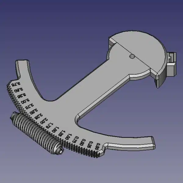
I’m terrifically excited about how well my latest star tracker design has performed with the Samyang 135mm lens. The only problem is… I can’t stop thinking about that backdrive. Seriously, it has wrecked more than a couple of night’s sleep for me over the past week. I know there are many solutions to this problem. I’m just not crazy about any of them. But today I’ll detail my approach to managing my star tracker backdrive.
What is Backdrive?
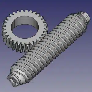
Let’s start by defining the problem. Worm gears transfer motion between two, non-parallel axes. The worm is a screw-like gear with a continuous thread(s). This gear meshes with the worm wheel which is normally, a helical involute gear. Therefore, worm gear pairs yield high gear reductions with high torque increases which is why they are popular for star tracking mechanisms. Typically, the transfer of motion is unidirectional. That is, the worm as an input can drive the worm wheel however the worm wheel as an input cannot drive the worm. This is known as self-locking and is a function of the frictional force and the tangent of the helix angle of the worm. When the tangent of the helix angle becomes sufficiently small, the worm wheel can overcome the frictional force and drive the worm gear. This is called backdrive, or the worm is said to be backdrivable.
Sometimes, backdrive is desired. But in the case of astrophotography, you don’t want the weight of your camera system to be able to feed back through the tracker. Unless of course, you’re looking for an excuse to buy new gear :). But seriously, you don’t want your camera equipment moving in an uncontrolled manner. That leads to damage. So when I designed this version of the star tracker, I chose a worm with 6 threads and a worm wheel of 300 teeth for ease of 3d printing. Unfortunately, this means the worm is easily backdrivable because of the small tangent helix angle.
Managing Backdrive
The good news is that backdrive is manageable. The bad news is that all the various solutions have their own unique drawbacks. So obviously, tradeoffs need to be considered carefully. I really only considered 2 approaches as viable but I recognize these aren’t the only options.
Add a Physical Brake
The first option I considered is to add a physical brake to the star tracker design. Something that manually locks the star tracker in its current position where no amount of load will backdrive the worm and spell certain doom for my camera. Absolutely doable. However, there are a couple of drawbacks to this approach. First, it’s additional complexity added to the design. Second, enabling and disabling a physical brake is another step in the astrophotography process. I can totally see forgetting about the brake on a dark and cold night. Would the tracker break if it ran with the brake on? No pun intended, but I just don’t know. And finally, what happens if I lose power? I’d have to do something pretty tricky if I wanted this kind of fail-safe.
Change the Worm
It goes without saying that the best way to deal with a problem is at its source. So redesigning the worm is kind of a no-brainer when managing backdrive. But here’s where things get interesting. Redesigning the worm is easy and theoretically will work. Can it be printed well? That is the million-dollar question!
I designed the first worm with 6 starts. With 6 threads, the lead angle for my worm design came out to be 22 degrees. And this was important to me because it meant that I could print the worm gear confidently without adding supports. No supports equals a smoother finished surface which means smoother and more consistent operation – as demonstrated from my initial tests. Fewer worm starts yield a smaller lead angle which is good, but it also reduces the overhang angle of the print which isn’t so good when printing without supports. 30 degrees is the “normal” cutoff before needing support and I was already pushing it at 22 degrees. So really this comes down to whether or not I can print a suitable gear with smaller overhang angles.
Choosing a Solution for Managing Backdrive
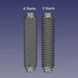
I didn’t have much of a choice in the end and I was going to need to modify my worm. I decided to go with 3 starts on the worm for a lead angle of 11.3 degrees. A comparison of the 6 start and 3 start worm gears are shown to the right. This is going to make the tracker less backdrivable but not necessarily self-locking. But, considering all the other design variables, the resulting gear reduction is as high as I’m willing to go at 100:1 (worm wheel of 300 teeth, worm of 3 teeth: 300/3). This ratio will be further enhanced using 1/16th microstepping but I’ll leave that design discussion for another day.
To print the new worm, I set my layer z-height to 0.06mm and slowed the print speed considerably. The hope is that the finer layer height and reduced speed will allow me to print a worm of sufficient quality without support. And despite taking over 3 hours to print, the gear came out really nice. But the proof will come with testing on the next clear night. I think things are going to be fine though. While I’m sure the new 3-start worm isn’t as dimensionally accurate as the 6-start worm, I expect the imperfections to average out due to the high number of worm teeth in contact with the worm wheel. The worm is still backdrivable with a fair bit of force when there is no power to stepper motor coils. But it remains static when I load my camera with the Samyang 135mm lens. This was really what I wanted to accomplish here.
Field Testing the New Gear Set
Thank the Lord for a small break in the weather that allowed me to sneak out with my second son to test the new gear set. Once again, I have high expectations for a successful test. But a funny thing happened about halfway through the night. The 12V power supply cut out after about 3.5 hours of shooting and… nothing happened. I call it a happy accident. My biggest concern using the Samyang 135mm lens was having this exact situation happen. And when it did, the tracker just sat there patiently waiting for me to turn the power back on. Perfect!!! I’ve succeeded in managing the backdrive for my particular setup. Now on to the results.
Doing a little maths similar to one of my previous posts, I calculate that with the Samyang lens and the Canon 250D sensor, there are approximately 3.5 arc seconds per pixel. Looking at the tracker gear train, the worm completes one rotation about every 14 minutes. This is the period of the worm. We set up the camera to shoot 24-second exposures which when factoring in the photo overhead was about 26 photos. Great, now I just load them into GIMP and do some pixel measurements over that period.
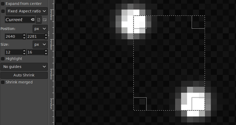
Roughly speaking, the straight-line distance between stars in their minima and maxima positions during the worm period is 20 pixels. This comes out to 70 arc seconds of periodic error peak-to-peak. That’s actually pretty impressive and I confirmed this over many hours of shooting +/- a couple of pixels. In fact, stacking the photos without aligning the stars reveals the very consistent pattern shown below. This represents 128 photos taken over 2 hours without performing any star alignment. I’m making the solid assumption that my polar alignment was not perfect which more than accounts for the observed drift over time.
Verdict on the Redesign
Well, it’s hard to argue with success. Observing a peak-to-peak periodic error of 70 arc seconds validates the design choices that I’ve made up to this point. And seeing the real-world nightmare of losing power and having the tracker remain statically locked in place was an added bonus. It certainly makes me feel better about letting the tracker work without having to babysit it – especially on cold nights!
I’ve still got quite a bit of work ahead of me on this project, but the hard work is done. Adding a polar finder, making an electronics housing, and finalizing the code are still ahead. I just need to sit down and pull this project across the finish line. But I’m nonetheless pleased to be at this point after years of working through countless star tracker designs. I think this one’s a winner!
