Hurry Up and Wait
I spent a few days in Studio mocking up a new version of the Lego Star Tracker. This proved to be a little more difficult than I was expecting. I’m really looking to create a robust upgrade to the whole system since I’m returning to one of my earlier designs. Remember what I said earlier about changing too many things at once? Well, there are a lot of changes in the Lego Star Tracker Version 5
As much as I liked the Lego Star Tracker Version 4, the balance issue I was facing made it clear I need to go in a different direction. I’ll share the gory details momentarily, but needless to say, I’ve just finished version 5. I don’t want to brag, but it looks real slick. I have no idea if it will work or not, but man, it’s certainly easy on the eyes.
I’m just about ready to start image testing, but that’s not my biggest issue at the moment. The clouds are back so there’s nothing for me to do but to sit back and wait.
Breaking It All Down
At its core, there are basically 3 main design elements. First, there’s the base. Second, there’s the gear train. And finally, there’s the load arm which holds the camera.
Looking at this from a redesign perspective, I already know I’m going to be changing the load arm and I’m returning to my earliest concept to try that again. I think I can make it even more compact, so I’m going to also be redesigning the gear train. And finally, even though I have some new ideas for the base, I think I’m going to keep it as is for now. I know I’ll change this eventually, but best to see if the new version of the tracker works before investing too much in this. If it ain’t broke …
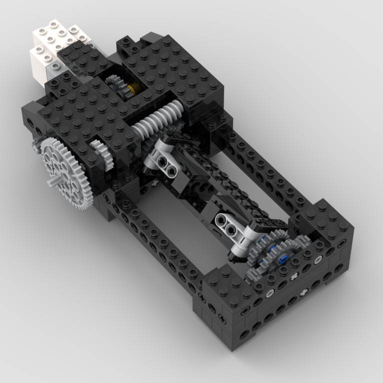
Lego Star Tracker Version 5 – Gear Train Simplification
I really like the gear train ratio of the previous version of 5760:1. The problem is, I designed that as a 2 x 2 x 2 x 3 x 2 x 5 x 24 gear train. That’s 7 paired gear elements that take up a lot of real estate. I know I’m keeping the 24:1 ratio at the output. I basically have 2 options at this point; one, find a better way to arrange the gear pairs, or two, come up with a different gear pair design.
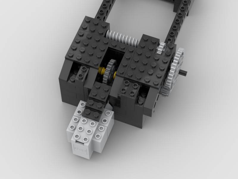
I went with number two for this iteration. I thought it would be worth trying to replace the 2 x 2 x 2 x 3 gear train with another 24:1 worm gear arrangement at the input. Brilliant! But … Worm gears always rotate your design by 90 degrees. Ok, just mount the motor at a 90-degree angle into the tracker. That works, but then I’ve got this funny little situation where my gear train is also offset by 1/3 the height of a Lego brick. That’s a total bummer.
I was getting frustrated with Studio and figured it’d be quicker to just try and build it. So I did. And what I ended up with was a very flimsy 24:1 x 5:1 x 2:1 x 24:1 gear train. Certainly not stable enough to continue, but good enough for a proof of concept. Awesome, now back to Studio where I quickly engineered a stable solution.
Originally, I was planning to encase all the gears, but I noticed something funny in Studio. If I leave the 5:1 gear reduction on the outside of the case, I can actually disengage the input from the output. This means I can effectively short circuit the whole drive train to more quickly center or “home” the load arm. It’s not an elegant clutch, but it will certainly work!

Load Arm Concept
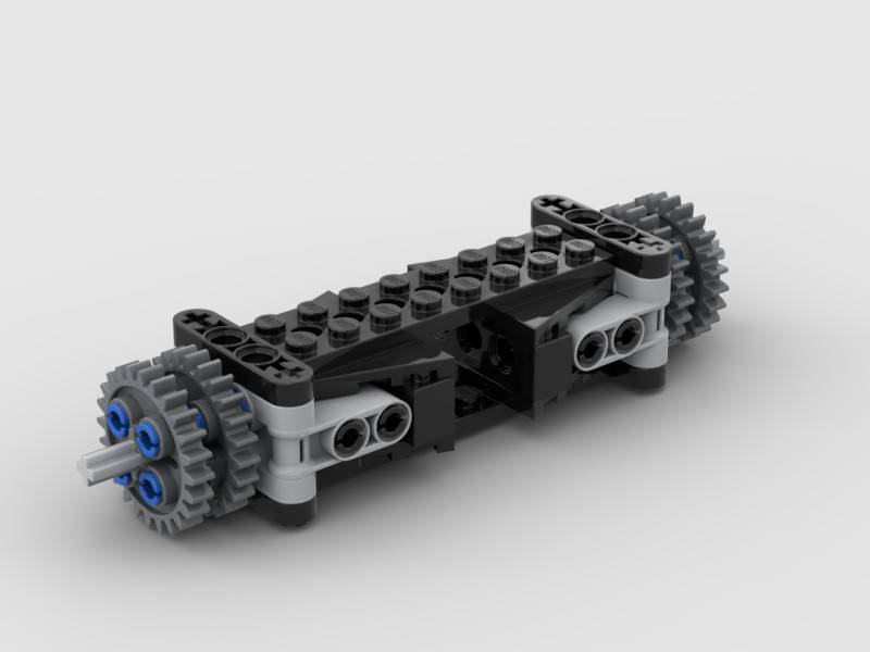
Basically, for the new load arm, I’m simply going to take the V4 load arm, double it, screw it to a block of wood and then bisect that with a 1/4″-20 rod about 25cm long. I’m also going to retain the 8 tooth gears from V4 to help keep the load arm centered in its cradle. Finally, I’ll add another 24 tooth gear below the axis on both sides of the cradle to provide a little bottom support as well.
Here’s what the load arm ended up looking like:

On Counterbalancing
This is really a calculus problem, but my head already hurts so I’m going to forego that route. Rather, I’m just going to assume that the camera, has a perfectly centered center of gravity, the 1/4″ 20 rod is weightless, the ball-head mount is weightless (cause it mostly offsets the rod anyway), and whatever I end up using for a counterweight also has a perfectly centered center of gravity.
These assumptions should be able to get me close to what I’m going to need as a first approximation.
The camera with the 50mm lens tips just North of 600 grams on a scale. And I can measure the distance from the center of the camera to the axis of rotation which is about 103mm. Converting those units I come up with about 5.4 lb-in or 0.61 N-m of torque. To balance this, I’d need about 367 grams of counterweight centered 170mm from the axis of rotation.
I’ll pick up some large steel washers the next time I’m heading past the hardware store.
Now if you’re reading this and thinking I’m playing a little too fast and loose with the numbers, well, guilty as charged. I’ll let you in on a little secret. I’m not trying to perfectly balance this rig. I’m trying to mostly balance this rig.
Everything I observed with the earlier versions of the tracker is still valid in this iteration. I actually want to be just ever-so-slightly out of balance so the Lego gears will be biased again on the downswing. I know this limits my imaging time, but right now, I don’t much care about 3 hours vs 6 hours of imaging time. Let’s get this working and then I’ll think about what else I can improve.
Besides, with all the assumptions I’ve made (which I know are not at all correct), there will still need to be some tinkering with the weights to get it all right. No sense in making a perfect calculation for a problem that doesn’t exist in reality. At this stage, I really just need to be in the ballpark +/-.
Yes, I Have Concerns
My biggest concern is that I’m supporting all this weight across 2 long Techinc bricks. I’m thinking I might be able to support this with a couple of simple trusses, but I’m not sure at this point. I can probably also double-up the long bricks to make it even more solid. But after putting it together, I’m not sure I’ll need either if I’m being honest. I’m going to adopt a wait-and-see approach here.
Next on my list is the load arm concept itself. I think it’s going to work just fine, but my Spidey-sense is tingling just a little bit and I really hope the whole thing doesn’t explode when I start my first imaging test.
Then, of course, I’m on pins and needles with the new gear train. The maths haven’t changed and I dramatically reduced the number of gears. That should mean less friction, less backlash, and fewer a-lot-of-other problems. But I can’t help but think I’ve maybe overlooked something obvious. Time will tell.
Here’s a look at the Lego Star Tracker Version 5.

Lego Star Tracker Version 5 – Inside Testing
In preparation, I’ve mounted the camera on the ball-head and fired up my Boost program to see how things would fare. I intentionally did not counterbalance the camera at this point, cause I wanted to see what the worst-case scenario would look like.
I was surprised at how well the rig performed. Yes, it’s clear to me that this wouldn’t image well at all like this as it’s a bit sticky, but it was surprisingly stable otherwise. I’m really hoping that counterbalancing the rod will make it operate more smoothly. Well, it’ll have to, or otherwise, I’m back to the drawing board.
That said, it’ll hold up to testing. Right, so now I just need to wait for some clear skies. And yep, looking pretty terrible over the next week. Well, that’ll give me some time to tinker and think a little more about my imaging setup.
Anyway, I’m looking forward to posting an update once I get out.
