Where to Begin
I have a general idea of how I want to use Legos to build a Lego Star Tracker. That said, I need to be careful and not get too far ahead of myself. The best strategy is to try to break this problem down into manageable goals.
Right out of the gate, I have two challenges ahead. First, I need to design a system that is stable and precise enough to transfer power from a Lego motor to offset a change in my target’s position by 0.25 degrees per minute. And second, I need to construct the device in such a way that it can handle the weight and torque required.
If I can’t overcome both of these challenges, I’m dead in the water on this project. But I have a few ideas based on some Lego pieces I fished out of the carpeting and from under beds that I can begin to test.
Lego Motor Selection
We have in our inventory a Lego XL Power Functions motor, a couple of Power Functions M motors, and a Boost Interactive Motor. I started by pulling down the specifications for these motors online to get a sense of what kind of gear train I’d need to build.
Well, I spent all of about 2 seconds making a decision. That is because I learned that the Boost Interactive Motor can be stepped in 1-degree increments. Man, I love nice numbers. This is going to simplify my design immensely. I’ll be able to control my input drive motor to deliver very precise output movements. The only downside, if you can call it that, is that I’ll need to use the Lego Boost App to control my tracker. I’m cool with that.
Gear Train Design
I need to create an output that will rotate something (to be designed) by 0.25 degrees per minute. That is 360 degrees divided by 1440 minutes in a day. Unless I’m being daft, it seems to me that the simplest solution would be to simply gear down by 1440 which means that for each 1 revolution of my input motor, I’ll get 1/1440 of rotational movement at my output.
That gear ratio will allow me to incrementally rotate 90 degrees every 15 seconds, or 45 degrees every 7.5 seconds, and on and on… That seems plausible. Now I just need to build a gear train with a 1440:1 ratio (1440 revolutions on the input will equal 1 revolution on the output)
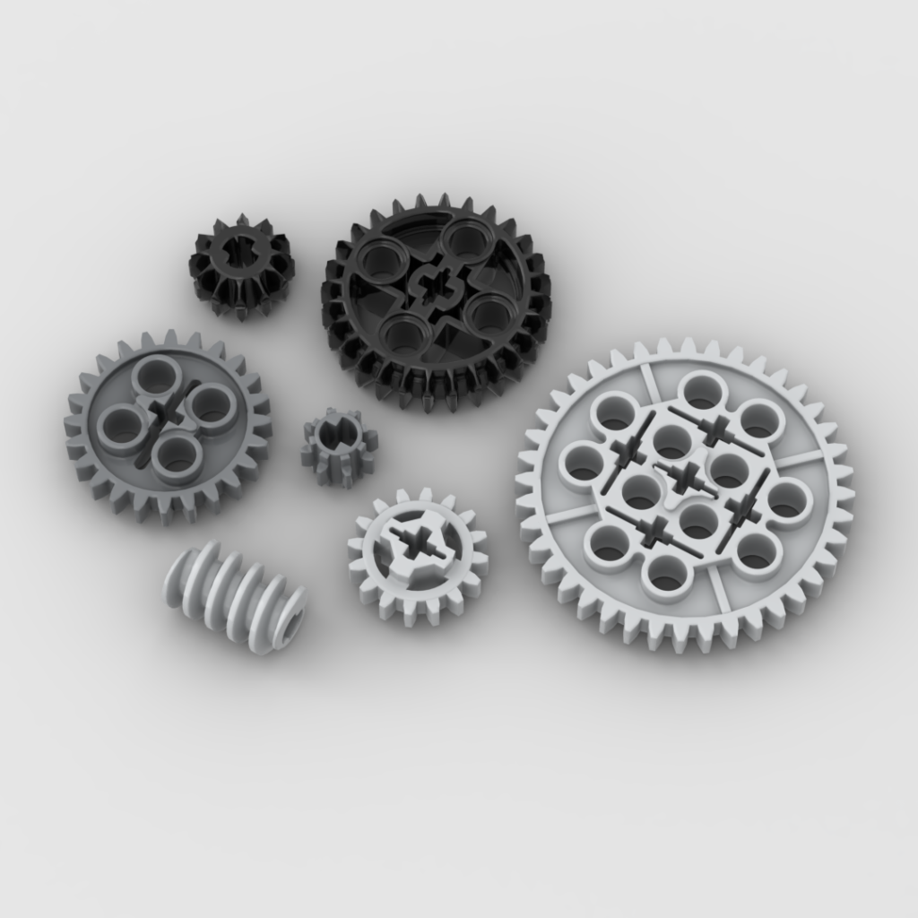
Awesome, well, kind of. It took me two days to find a combination of gears that will yield a 1440:1 ratio. This was based partly on the gears that I have on hand and the odd little fun fact that there are few Lego gear combinations that will yield a 4:1 gear ratio. But with a little trial and error, and a few sheets of notebook paper, I found a combination that works.

If I use a worm gear, I can gear down by 24:1 (worm gear driving a 24 tooth gear). So 1440 / 24 = 60
I can gear down further with a 5:1 (8 tooth gear driving a 40 tooth gear). 60 / 5 = 12
Next, I can gear down with a 3:1 (12 tooth gear driving a 36 tooth gear). 12 / 3 = 4
Why Lego, why aren’t there any simple 4:1 reductions? Yeah, I’ll finish up with a couple of 2:1 ratios (8 tooth gear driving a 16 tooth gear) 4 / 2 = 2, and 2 / 2 = 1
2 x 2 x 3 x 5 x 24 = 1440 Yay me!
Beauty of Worm Gears
I’ll position the worm gear stage at the end of the gear train for a couple of reasons. First, worm gears are input-only gear systems, which means my output stage can’t effectively drive back into my system. This will be important if I have balance issues at my output. Secondly, worm gears have very low backlash (the back and forth play between interlocked gears). This will reduce some of the slop at my output.
On Backlash…
It’s obvious to me at this point that Lego gears are very sloppy. I mean they’re awesome, but they’re not precision designed for purpose. This allows for flexibility in their use which is an important feature. But I can see that the slop in some of my gear combinations is probably as much as a couple of degrees. Yikes, I’m trying to control the output to 0.25 degrees per minute with gears that can slip by degrees!
Ok, new challenges. I think I have some thoughts on how to manage backlash, but let’s just crack on and see how it goes.
The Output Stage
My first idea is to run an axle through my final 24 tooth gear which connects into a “box” built with technic pieces that I can secure to a piece of wood through the holes using 3mm screws. I harm no Legos! I’ll support that on the opposite side using the same idea. The secured wooden piece will be run through with a 1/4″ 20 threaded rod that I can secure my camera to and counterbalance as needed.
I’ll then build little walls around this box to give the system some stability. This sounds great. The only design drawback is that I’m intentionally limiting the range of movement at my output to about 90 degrees total. That would equate to about 6 hours of maximum tracking time. I think I’m OK with that right now.
Let’s Put it Together
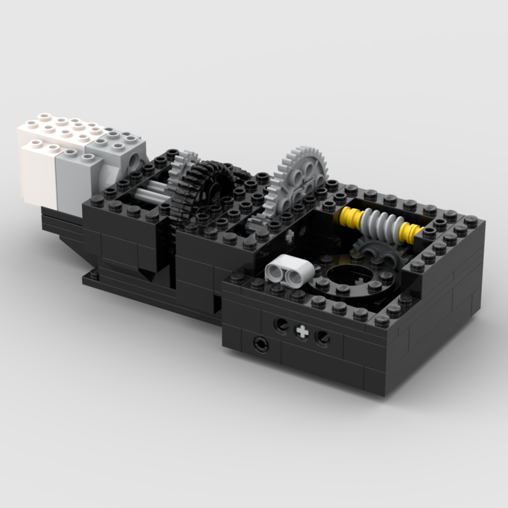
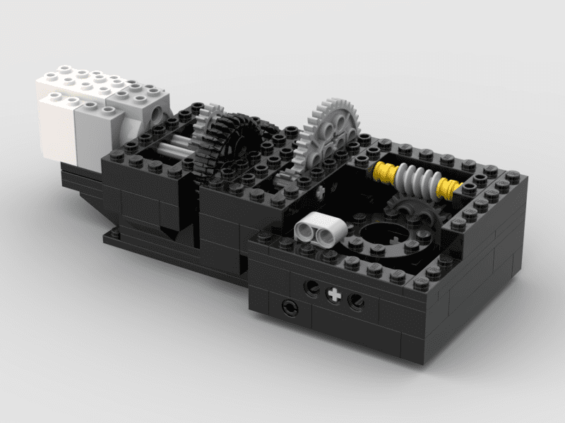
I decided to mock my design up in Studio to help with conceptualizing my project. It’s better than hunting through piles of Legos looking for what I think might be the right pieces. I suppose it took a couple of hours to arrange all my pieces, but it was time well spent and helped simplify my build. Here’s a quick peek.

Next, I constructed the “box” or more aptly the cradle to hold a wooden dowel, cut my dowel to length, screwed my Technic pieces to it, secured the threaded rod through the dowel, and built the whole device according to my virtual instructions.
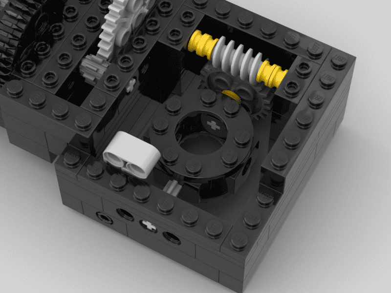
Here’s a close-up picture to help you see what I’m talking about.

A quick thought on polar alignment. I’m initially planning to be able to mount this to a tripod head and will use a similar Technic-screw-through-the-holes technique to secure this to the tripod using a t-nut through a wooden base. Cool!
Lego Star Tracker Version 1 – The Verdict is In!
Epic fail! This design isn’t going to work. Not even close. After putting it all together, it became immediately clear that my box solution with the Lego axle on the output isn’t going to be able to take the weight of my camera. I mean it will hold. But the flex that I’m seeing in the output system is on the order of 15-20 degrees of movement! No way I’m even going to try to put my camera on this thing.
But I’ve learned something very important. The weak part of my design (at this point) is that Lego axles aren’t rigid enough to stand up to the forces. I think I’ll try to support the axle with round bricks in the next iteration.
The good news is that the gear train I designed is working great. Also, the housing structure that I built is very stable and tight. I have no concerns about the integrity of the housing right now.
After putting it together, I found I’m not a fan of the “box” approach. The limiting movement is clunky as designed in this iteration and I’m not sure I really want to fuss with it moving forward. I’m thinking I might try to design an open face structure to mount the camera.
So, let’s junk this design, hit the drawing board, and try again.
