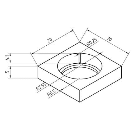
I’m going to spill the beans today to share how to create a perfect 3D-printed interference fit bearing housing on FDM printers. Might as well since I can’t be outside imaging… The struggle is real. When I started 3D printing trackers, I couldn’t figure out why my brand-new bearings weren’t delivering the smooth rotational movement that I was expecting. There always seemed to be some kind of pinching, clicking, or uneven movement in my shafts. If I messed with the dimensions of my bearing holes, I got smoother movement, but the bearings wouldn’t stay put in the housing. After burning a few calories with my cranial computer I had a eureka moment. I found a way to print perfect interference fit bearing housings. And this is what got me over the hump with my latest design.
Before We Begin
It should be noted that printing a successful interference fit bearing housing on an FDM printer begins with the proper tuning of your 3D printer. You really need to be able to print dimensionally accurate parts with your printer. So don’t skimp on calibrating your printer for optimal results. You want to print your design, not design around your printer! This is key if you want your designs to be reproducible.
It’s Not as Hard as You Think
The goal is to print a dimensionally accurate hole in a part to press fit the bearing into place. Sounds simple enough. But it’s not actually. FDM printers leave a little excess material wherever they start or stop printing on a layer. As the layers of your part print, these locations form a seam. Now it’s possible to control this by further tuning your printer settings or randomizing the seam locations to kind of hide them on each layer. The former requires a trial-and-error approach while the latter leaves a print surface that looks like it has contracted smallpox. Neither is ideal.
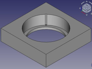
However, it’s possible to line all the seams up in a way that doesn’t interfere with the bearing hole by creating a little pocket for the seams to fill. And so the trick is to “budget” space in your design for the seam. You can see this in the example design to the right. The pocket alleviates the point stress formed along the seam on the outer race. Now if you’re using a large bearing with a thick outer race, this isn’t going to be an issue. But if you’re using smaller bearings with thin race walls, this is a must.
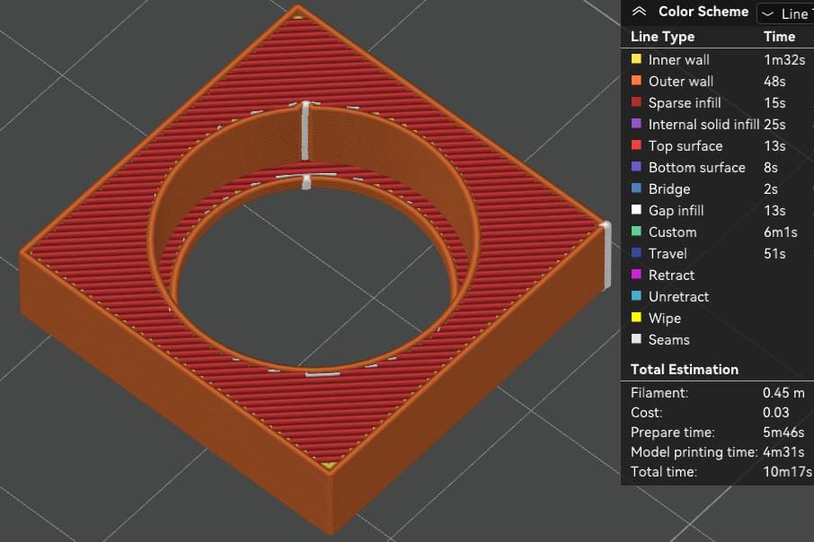
Most slicers have a feature that allows for seam management. Some even let you choose precisely where the seam should go. Depending on your slicer this is easily accomplished as shown in the image below. Notice how the seam (white line) perfectly fills the pocket where the bearing will sit.
Test Print for a 6700-2RS Bearing
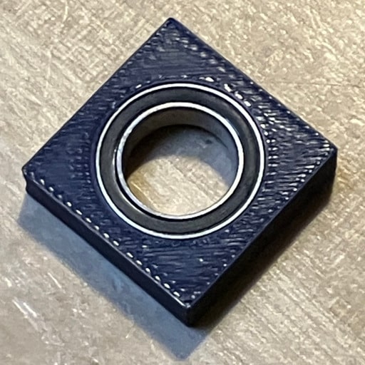
The 6700-2RS is a 10x15x4mm bearing that I use a lot. I find that the 10mm bore diameter is a good tradeoff between size and being able to print a rigid shaft. Regardless, I always start with a test design and print. There is nothing worse than waiting hours for a print to finish only to realize that the bearings won’t fit right. So the test design for this tutorial is shown below.
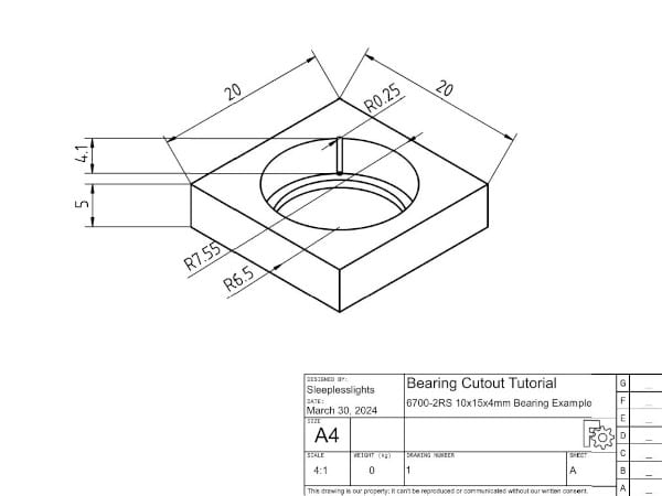
This bearing has a 15mm diameter and 4mm height so I’m starting with a 20x20x4mm box. For my printer’s calibration and settings, I oversized the bearing housing hole radius by 50 microns for a radius of 7.55mm in the design. I find that this works quite well as a standard for my printing setup. I can always tweak the hole diameter settings in my slicer after my test print if I need a looser or tighter fit. This is important because if you’re swapping out plastic rolls, your dimensions could change ever so slightly.
Next comes the important part. I cut out a 0.25mm hole in the part on the outer radius of my housing hole. This is the pocket that the seam is going to fill. Additionally, I sink the bearing hole 0.1mm past the bearing height. These two design points ensure that the bearing will be fully seated in the bearing housing hole below the surface of my part with no interference from the seams.
Finally, I leave an approximately 1mm radius lip at the base of the bearing to act as a backstop and to keep the bearing properly aligned in the housing hole. And below you can see what the test print looks like. The bearing fits snugly in place with real smooth operation!
Why a Perfect 3D-Printed Bearing Housing Matters
For most applications, it probably wouldn’t. However, I’m chasing precision movement where even tiny misalignments end up being noticeable in the photos that I take. Don’t get me wrong… I’m not being unrealistic in my demands for what my printer can produce. Just saying that at the scale and speed of movement that I’m working with, millimeters and microns can’t be overlooked. And this little fix ended up making a big difference in my tracker performance.
Creating pockets for seams in your bearing housing designs will ensure that your bearings stay aligned and rotate smoothly. That really is half the battle in designing something like a star tracker. Now you know.
And for what it’s worth, this little trick works great for any printed parts that you’re joining together as well. By designing pockets and lining up the seams in those pockets, you’re always assured of meshing your printed parts according to your design. Not the limitations of your printer!
